| |
|||||
Workbench: |
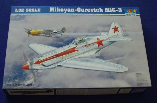 |
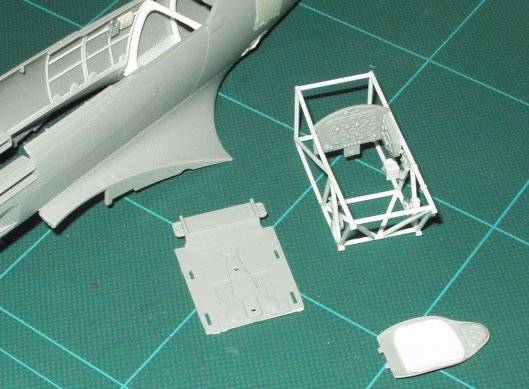
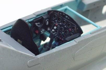
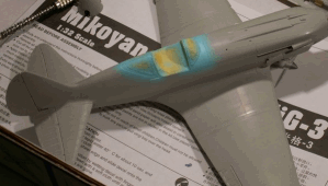
When Trumpeter released their long awaited MIG-3 I was very pleased to read on various web sites that the fit and detail were being rated highly by those fortunate modellers in the States who were able to get their hands on it a few weeks before the arrival in the United Kingdom.
Having got my hands on an example I set about comparing it to the scale and general arrangement drawings that I have, and indeed all looks well. The kit will, from the box, build up to make a representation of a later production MIG-3. The main difference between this and the earlier version being the lay-out and number of bulges over the guns on the upper engine cowling; there is also a difference in the exhaust pipe shrouding, etc. Before I hear the cry of "heretic" and the smell the burning torches, there are indeed other differences and these are extremely well detailed in the work by Massimo which can be found on his new site. I must give a special mention to Massimo who has been of great help with the research for this model, and has been prepared to supply me with photos showing key points and to put up with my endless questions. Oh well, thats what happens when you know an aircraft so well, my friend....
I had every intension of putting the big MiG away for a later date, but I found myself being drawn to the box as if it was calling me, the result being that I started to cut plastic. So much for the plans of mice and men.
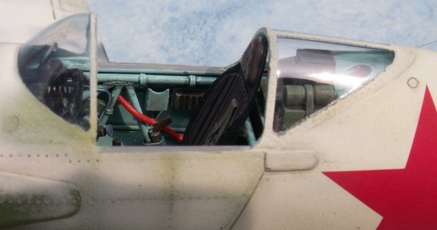
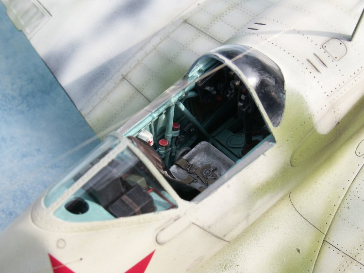
So far, the only area that I feel needs to be improved is the cockpit and it was with this in mind that I started to work on the model (albeit on an ad-hoc basis). Thus, a little was done one night, then nothing the next three, and so on, as I have other projects under way.
It was during one of my infrequent email sessions with Erik that the idea of showing the progress of this model on the VVS web site was talked about. The idea in this case being that postings to the site will show the model's progresses and the work carried out in my effort to improve an already good kit. The intention is for me to supply not only photographs but also drawings of the various parts made to detail the cockpit, along with a scale, so that anyone who wishes to can replicate--or even improve--what I have done.
How long this process will run for, I do not know. It may be until the
model is completed, or might be just until the cockpit is completed? How
frequent the postings will be I do not know, but as the model and the various
bits are made, you will be the first to see them.
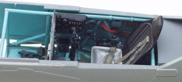
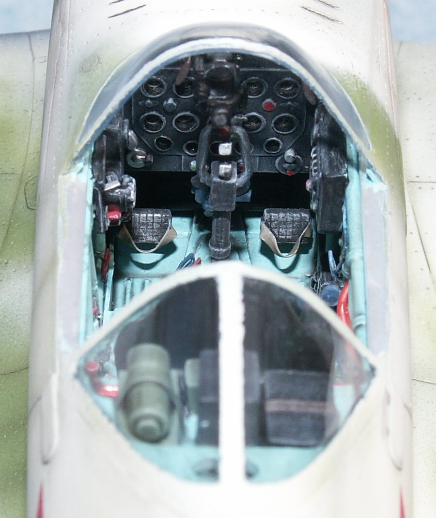
Detailing the PIT
Areas to be corrected / detailed
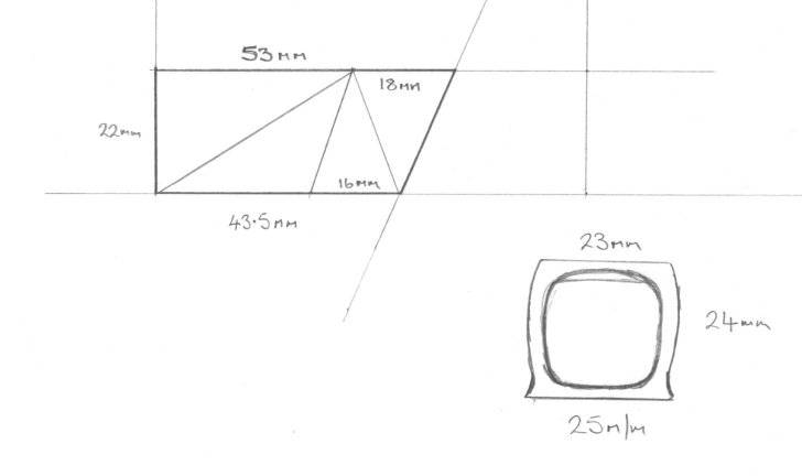
Please refer to the drawings attached for greater clarity:
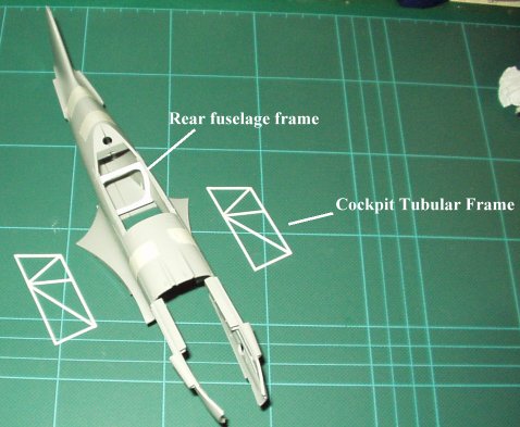
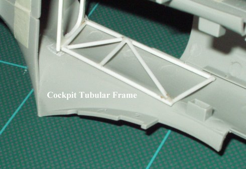
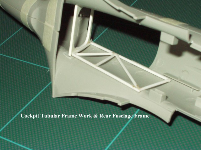
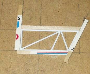
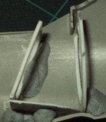
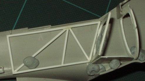
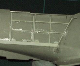
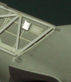
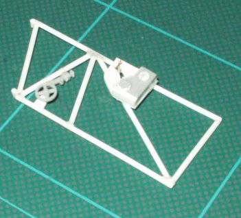
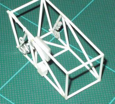
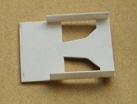
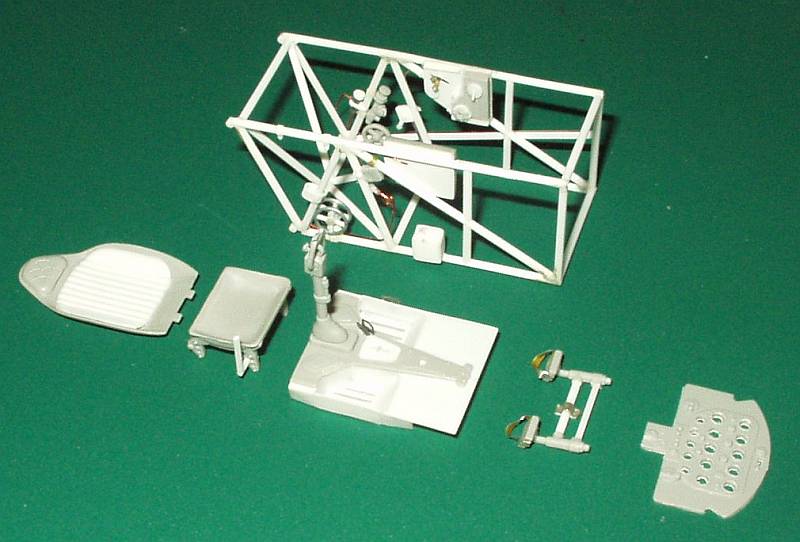
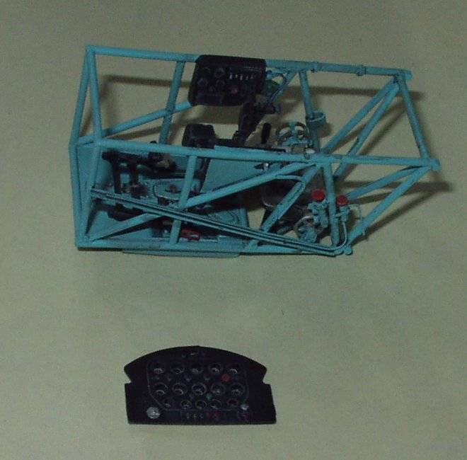
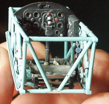
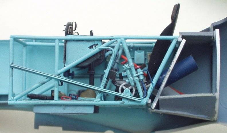
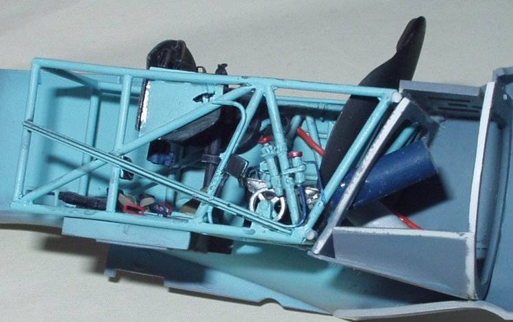
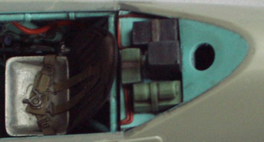
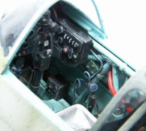
The first components of my attempt to detail the cockpit were the cockpit tubular framework and the forward frame of the wooden rear fuselage section.
[Note that it is my intension to post drawings with measurements to allow any who wish to replicate or better my work to do so; the photos attached show the components at their present stage of development, and they are not finished yet. There is one upright frame member to add but its position will be finalized later. It goes from the lower longeron straight up behind the instrument panel]
 |
 |
 |
 |
 |
 |
 |
 |
 |
A drawing with dimensions is attached.
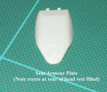
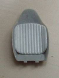
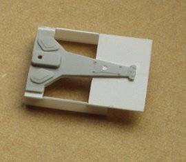
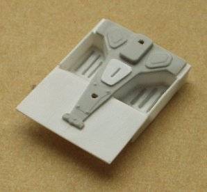
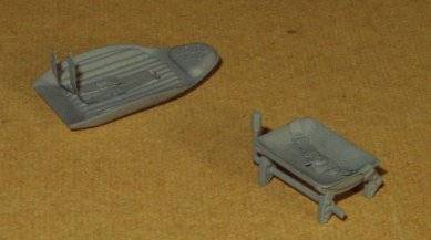
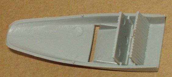
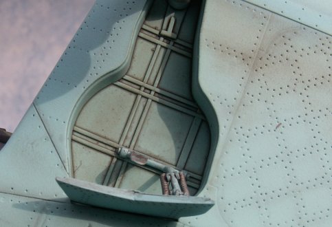
Kit seat, rear armoured back plate. All the sharp edges/folds have been removed with a sanding stick, the indent / recess in the rear of the palte where the head rest joins has been filled and filed smooth at the same time the overall thickness has been reduced.
10 Feb 2004 Note: The measurements of the spade shaped frame
should be 25mm by 21mm not as I have written 25mm x 12mm.
 |
 |
 |
 |
 |
|
 |
 |
 |
 |
 |
 |
 |
 |
 |
 |
 |
I would like to extend a very special thanks to Massimo who has helped
me more than words can express, thank you Massimo I owe you a drink if
we ever meet.
 |
 |
 |
|
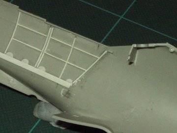
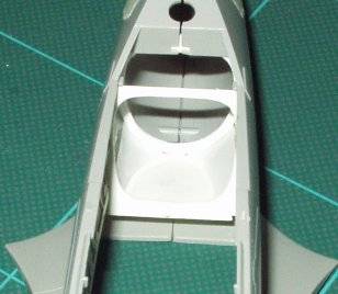
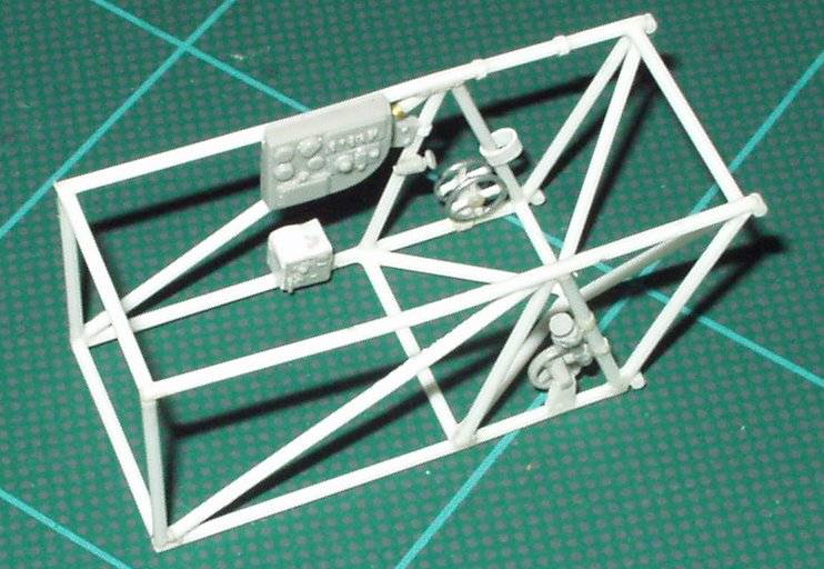
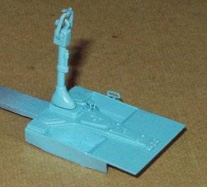
Carefully cut out the central raised Y shaped section from the kit part, the remainder can be placed straight in the waste bin. The Y piece is now sanded down to reduce its thickness being careful to keep the underside level, when you have reduced its thickness glue it to a piece of 15 thou palstic card that is 21mm wide and slightly longer than the Y piece (This will allow you to trim it to size when fitting it into the frame. The wells now need to be VERY carefully cut out, keep the sections you have removed as they will form the well floors. Add sides to the wells as seen in the photo which results in you having holes, using 15 thou strips of plastic card that are 4/32 inch wide (Approx 4mm) add the well walls from the underside, NOTE the end plates that are nearest the rudder pedals should slope backwards from were they join the floor plate. The last thing that is required on the wells is to add the floor sections using the cut outs, BUT BEFORE THIS DONE you are required to represent the stiffening ridges formed in the floor plates, this was done by taping the floor plates in place and then drawing around the inside of the well to mark the actual area that will be visable when they are attached. Remove them and now add stretched sprue to form the 3 ridges found on the original. The last thing required at this point is to add the missing plate that is located between control stick and rudder pedal mounting points, this plate had a off center slot cut in it throught which an indicator needle protruded, If any one reading this can confiirme just what this indicator was for- PLEASE contact me and share your knowledge.
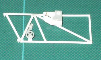
I would also like to thank one of the site visitors would is following these posts and is building what looks like a fine model of a MIG-3 himself, this gentleman was kind enought to send me some photos and to ask me to explain how I had made the trim wheels , thank you Maarten.
Trim wheels are made as follows:-
Wrap / roll soft wire around a rod ( A paint brush handle was used )
then remove what now looks like a spring off the tube , cut through with
a new blade or sharp side cutters, push the ring flat on the bench or with
plain pliers, super glue the ends and you have the circle, now with super
glue attach a cross piece of plastic rod from say 12 to 6 o'clock point,
then attach two more from 9 and 3 o'clock and you have your trim wheel.
 |
 |
 |
 |
 |
|
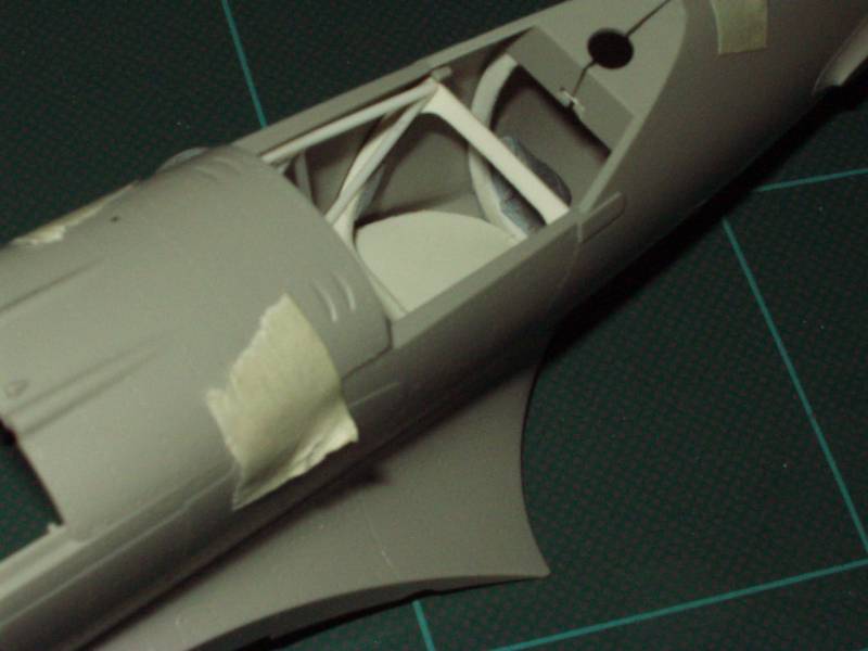
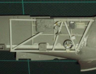
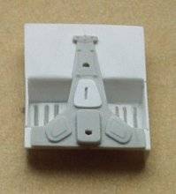
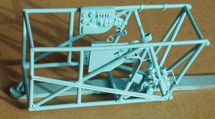
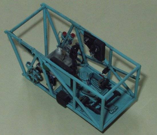
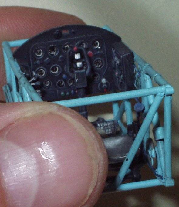
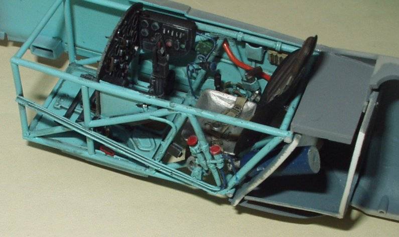
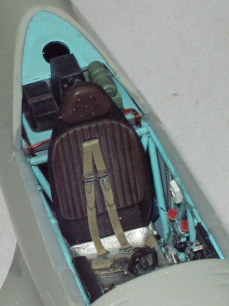
 The
majority of work invovled in correcting / detailing the cockpit is now
completed as you can see from the photograph, the next step will be to
alter the lower panel on the main instrument panel as compared to my drawings
it is incorrect. This will be followed by the addition of smaller details
on the main panel section such as gun cocking handles after which the panel
will be painted prior to the application of photo negative instruments
dials (Spares from an Eduard I-16 detail set which I never used). Having
added some detail to the rear section of the fuselage such as air bottle
mounting points and a set seat belts to the seat its self it will be time
to paint all of the sub sections ready for assembly. I apploigise for the
delay but I will admit to have been spending some time on my other projects,
a Belgian F-104G and a VVS MIG-29.
The
majority of work invovled in correcting / detailing the cockpit is now
completed as you can see from the photograph, the next step will be to
alter the lower panel on the main instrument panel as compared to my drawings
it is incorrect. This will be followed by the addition of smaller details
on the main panel section such as gun cocking handles after which the panel
will be painted prior to the application of photo negative instruments
dials (Spares from an Eduard I-16 detail set which I never used). Having
added some detail to the rear section of the fuselage such as air bottle
mounting points and a set seat belts to the seat its self it will be time
to paint all of the sub sections ready for assembly. I apploigise for the
delay but I will admit to have been spending some time on my other projects,
a Belgian F-104G and a VVS MIG-29.
 Progress
has been slow recently due to other commitments, don't you hate it when
life interuptes your pleasures!
Progress
has been slow recently due to other commitments, don't you hate it when
life interuptes your pleasures!
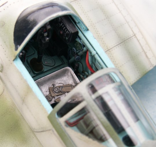
The cockpit and fuselage interiors have now been painted and await detail painting of the various components. I have choosen to use the advice regarding interior colouration given by Erik Pilawskii in his book on Soviet Fighter Aircraft Colours, I have accordingly painted the cockpit interior using AII Underside Blue and the rear fuselage wooden section in W.U. P. All of the paints used are those manufactured and marketed by White Ensign Models. I feel that I should say a few words about these paints, I don't normally use enamels having converted to the other side a number of years ago, but having used these paints I am no longer sure in my previous total conviction that there was only one paint and that it was water based.
 These
paints spray extremely well, the spray gun does not clogg up, the finish
is very fine and the paint normally dries to a smooth satin finish (more
about this later) and covers very well, the only negative point is the
extended drying time which I have found can be measured in days and not
hours, I have been told and I have read that this can be reduced if you
add a little Cellulose thinners in with the normal enamel thinners when
mixing up, I have not had the nerve yet to try this as I am well aware
of my luck and what cellulose can do to plastic. I have noticed that the
drying time seems to depend on the colour and the amount of thinners added,
some colours appear to dry faster with more thinners some seem to take
longer, it was also at this time in experimenting with thinner ratios to
see what effect they had on drying that I noticed that if you add more
thinners to the paint it dries to a gloss finish. I can live with the drying
time and use a drying box, this is simply a large plastic lunch box with
a lid, spary model place in box , put lid on to prevent dust getting onto
wet paint and put box in airing cupboard, in England that a small cupboard
usually placed over the central heating / Hot water tank to keep towles
ect aired and fresh smelling, end result is the temperature in such a cupboard
is quite warm but not so high as to cause damage to the plastic kit and
helps your paint dry.
These
paints spray extremely well, the spray gun does not clogg up, the finish
is very fine and the paint normally dries to a smooth satin finish (more
about this later) and covers very well, the only negative point is the
extended drying time which I have found can be measured in days and not
hours, I have been told and I have read that this can be reduced if you
add a little Cellulose thinners in with the normal enamel thinners when
mixing up, I have not had the nerve yet to try this as I am well aware
of my luck and what cellulose can do to plastic. I have noticed that the
drying time seems to depend on the colour and the amount of thinners added,
some colours appear to dry faster with more thinners some seem to take
longer, it was also at this time in experimenting with thinner ratios to
see what effect they had on drying that I noticed that if you add more
thinners to the paint it dries to a gloss finish. I can live with the drying
time and use a drying box, this is simply a large plastic lunch box with
a lid, spary model place in box , put lid on to prevent dust getting onto
wet paint and put box in airing cupboard, in England that a small cupboard
usually placed over the central heating / Hot water tank to keep towles
ect aired and fresh smelling, end result is the temperature in such a cupboard
is quite warm but not so high as to cause damage to the plastic kit and
helps your paint dry.
 |
 |
 |
 |
 |
 |
 |
 |
 |
|
 |
 |
 |
 |
 |
|
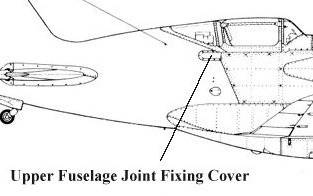
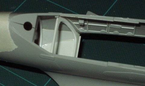
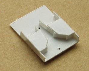
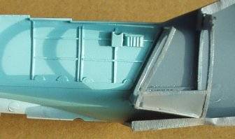
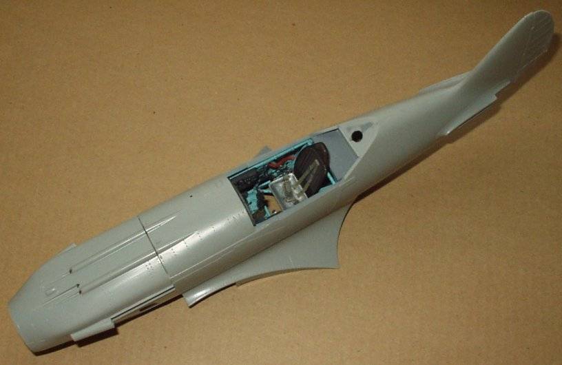
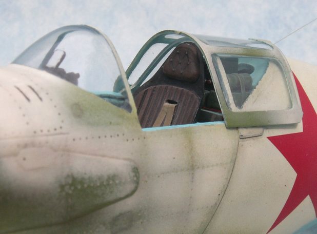
The cockpit frame was fixed into one half of the fuselage prior to the
two sections being glued permanently together. The photo shows the model
after the joining of the two fuselage sections has been completed, the
forward upper nose panel has also been fixed into place. I must say that
I have read various comments about Trumpeter kits, some of the less than
kind comments seem to dwell on the fact that Trumpeter is a company from
a Communist (OH lord help me, I have mentioned that word) country, so what,
Credit were it is due, THE FIT ON THIS KIT SO FAR IS EXCELLENT, even the
dry fitting shows no problems waiting to ambush the modeller yet.
 |
 |
 |
 |
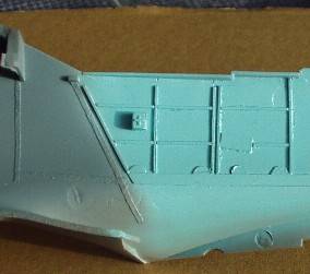
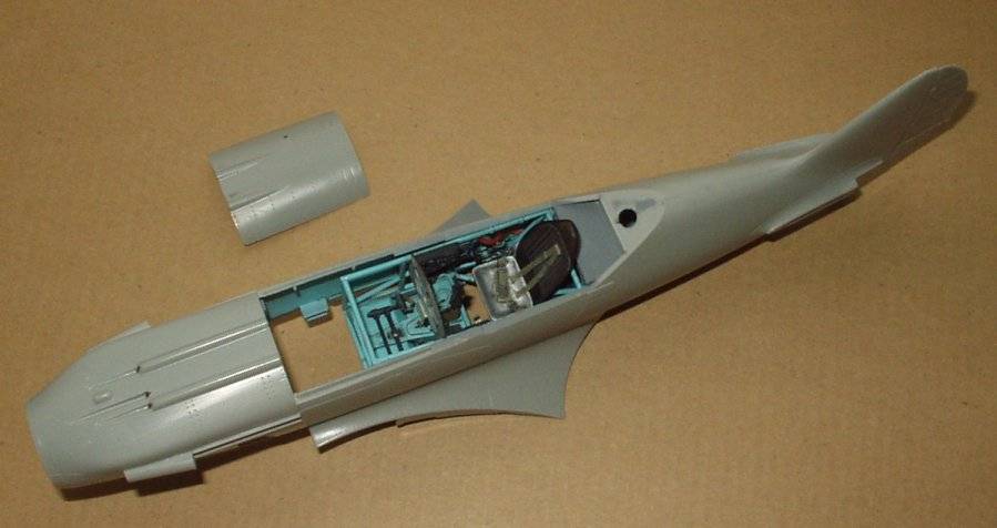
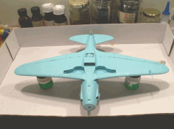
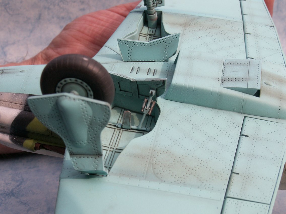
Update 16 August 2004
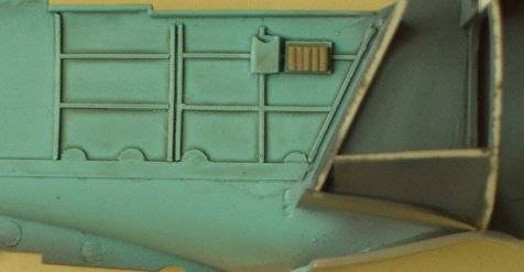
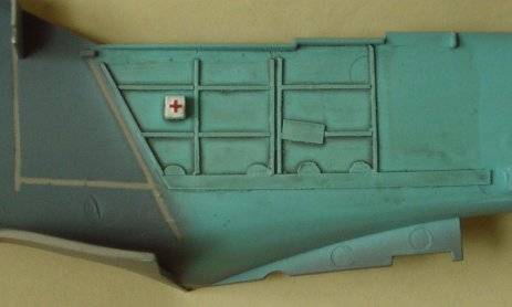
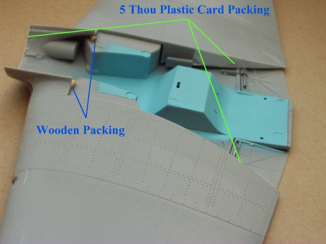
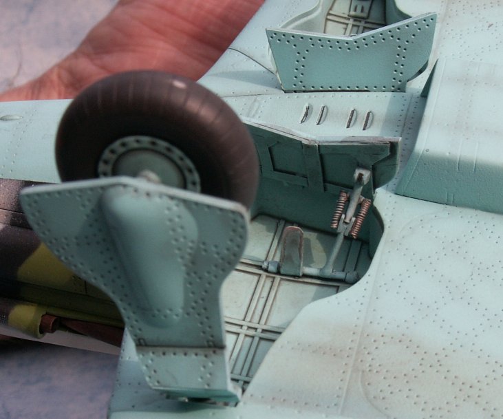
The fit so far has been excellent. The only areas that have received any packing at this point are the very front section of the wing to fuselage joint and a small section on each wing root (see photos).
 .....
.....
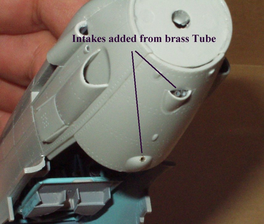
Added detail includes the drilling out when required and addition of brass tube to the lower engine cowling bulges ( see phots).
Fit alert:- I have just started to test fit and fix the wing leading
edge slats, be carful if you intend to model them shut ( I believe this
is really the only option as to the best of my knowledge the MIG-3 slats
were normally closed on the ground, in fact I believe that the
Soviet method of slat deployment was totally different to that found
on German aircraft such as the Me-109). TAKE GREAT CARE AND SPEND LOTS
OF TIME DRY TEST FITTING ; THEY ARE THE WORST PART OF THE KIT SO
FAR BUT CAN BE MADE TO FIT WITH TIME AND CARE.

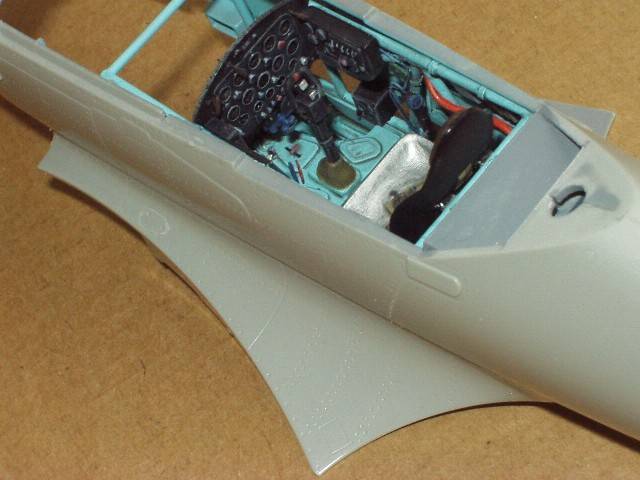
Update 11 September 2004
Construction continues slowly. Some sub-assembly painting is under way,
the paints used being those excellent colours supplied by White Ensign
Models. Some minor detailing is still being carried out to the model,
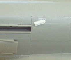
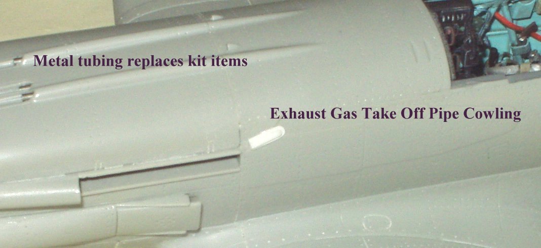
and you can see from the attached photos that I have now added the cowling
that covered the Exhaust Gas Take Off Pipe. This unit appears not to have
been fitted to all MIG-3 production aircraft; this might be due to early
production airframes not being spec`ed with this effective if simple fire
suppressing system (cooled exhaust gas is piped into
the fuel cells, as it is inert it will not / cannot support combustion,
fuel tank gets hit with incendiary round--- result no explosion or fire
in fuel cell) or it might be down to the individual factories after the
move.
 ....
....
Update 28 September 2004
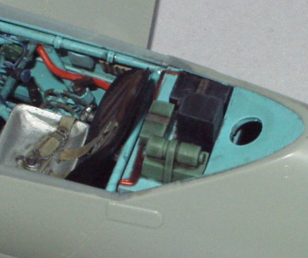
The built-and-modified radio set has now been painted and fitted to the rear shelf. The straps that go around the tool and battery boxes were made from the lead foil found around any good bottle of wine ( "..sorry, love, but I have to open this bottle of red as I need the foil... of course it will go off now that the foil has been removed, so that`s why I`m drinking it..."). Check your references before fitting the set, as a number of MiGs flew without the radio, even ones fitted with the mast. Also note that according to my plans the radio is taller than the kit item; in fact it is the tallest of all the units fitted on the shelf. The wiring is just some red coated copper wire I have had hanging around for the last 2 decades waiting to be used.
 ...
... ...
...
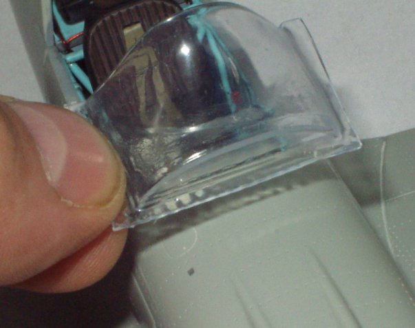
The other photos show the Partridge/Vill vac-form forward canopy section before being cut out and fitted. My research and subsequent correspondence with Erik and Massimo holds up my view that there were NO Rails running top to bottom, and that the MiG-3 front screen was in fact likely a 3-piece construction; the two side sections being curved while the front section was flat (though curved at the top), the front piece being bonded to the two side sections. The thin colourless line that can be seen in some photos is nothing more than light distortion as it passes throught the bonded area.
Update 15 December 2004
White Ensign AII Blue was applied to the canopy frame work prior to the fuselage being primed with "Halfords" grey plastic primer. When dry, the assembly was checked for any faults, a few being found and corrected. The fuselage was then given a second coat of primer, the forward canopy area receiving a third and fourth coating ( A.Sekularac's method to build up frame work / ribs; see his excellent build write up of the I-16, which can also be found on this site or in Scale Aircraft Modelling June 2004 vol 26 No4).
 ....
....
The underside has now been base coated with White Ensign AII Blue and awits weathering, ect, when dry.
At this point in time I feel that it is only correct to comment on the White Ensign range of paints (Note I said range, not just VVS colours). Sure, I helped bring the VVS range to life ( my part being very small compared to the ground breaking work carried out by E. Pilawskii), but when told they would be enamel I was a bit disappointed. I was no great fan of this type of paint, having replaced all of the enamels I had with water based paints several years ago.
Having received a set I felt I had to try them, so I armed myself with some "Daco" thinners. I applied my first colour and found it to be great paint-- it sprayed well with no clogging of the gun and the coverage was excellent. The surface finish has always been smooth satin, and with the addition of more thinners you can achieve an almost gloss finish some times. On the minus side was the cleaning up and the drying time. The drying time was less than most enamels I have used, and can be reduced even further if you can locate a supply of the old " AeroMaster" Enamel thinners. I was given mine by a good friend, and all round good guy, John Evans of the Avon IPMS (thanks John, and at last your name is in print without the word WANTED above it) or cut your thinners with Cellulose thinners, but be careful as cellulose eats plastic, so make sure you prime the kit.
Overall, these are very good paints and I would recommend their entire range to all modellers. White Ensign took a risk in this "Acrylic" world and in my mind proved that NEW don`t always mean better. I mean, after all how can a "Beef ??" Burger compare to Ferret Pie?...
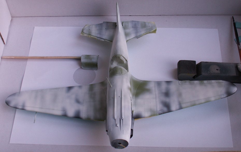
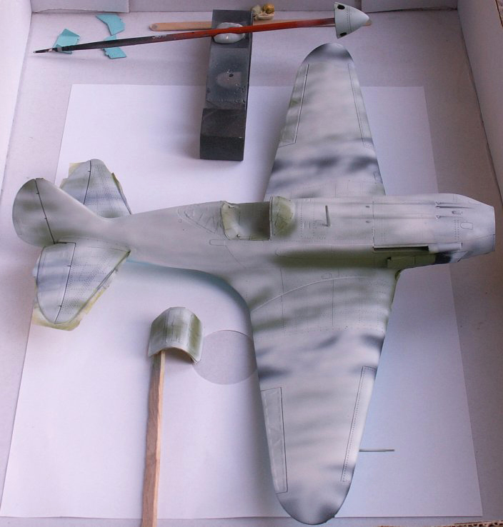
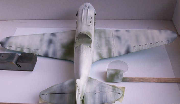
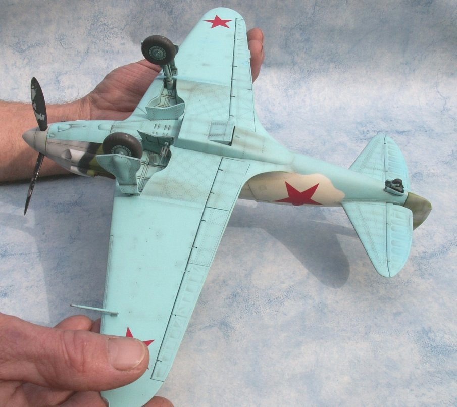
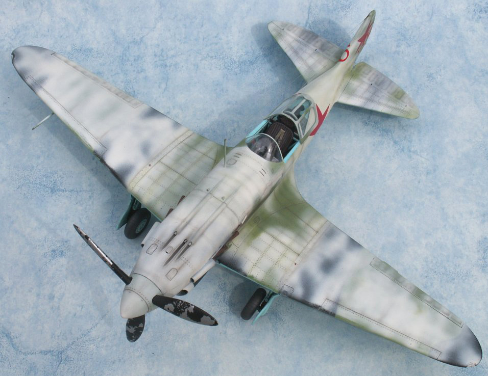
Update 24 January 2005
The upper scheme of AII Green and AII Black have been applied and allowed to dry for a week. I only spray during day light and that means weekends at this time of the year. Over this, an over-spray of white has been applied; this will later be gently rubbed back to expose more of the Green/Black scheme. If required, I will touch up the Green/Black and lower surface Blue with the spray gun, and only then will the weathering be applied. Please keep your fingers crossed! I hope it turns out-- winter schemes are not easy to do ( well not for me ), but if you manage it they are so pleasing to the eye.
Today (23rd January) I spent the best part of 3 hours in a very cold annex to my house trying to touch up some minor defects noticed after last week's white over-spray. It all went to pot, so in the end I took out my thinner soaked rag and wiped todays application of paint off. I only have chance to spray at weekends and I prefer day light any way, so a quick calculation ( I'm good at those-- never get the right answer though, but heck who cares?) and I reckon that if all goes right I should be able to commence weathering in about 3-4 weeks. That is one problem with slow drying enamels... For those who have been following this build, I am sorry that it has taken so long. Maybe I should have ended it with the cockpit? I am told that people have been born, grown up, had kids of their own and are now drawing their pensions while waiting for the finale part of the BIG MIG work bench.
 ....
....
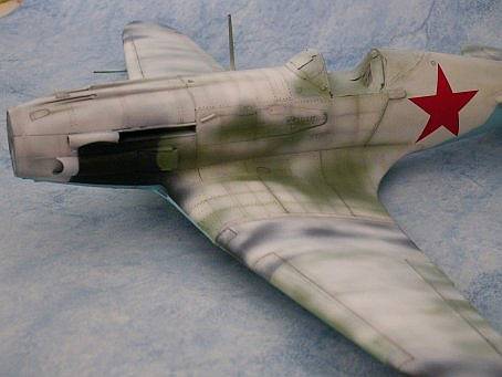
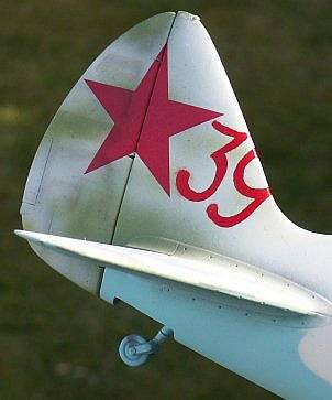
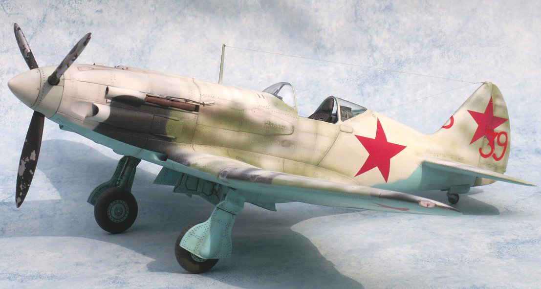
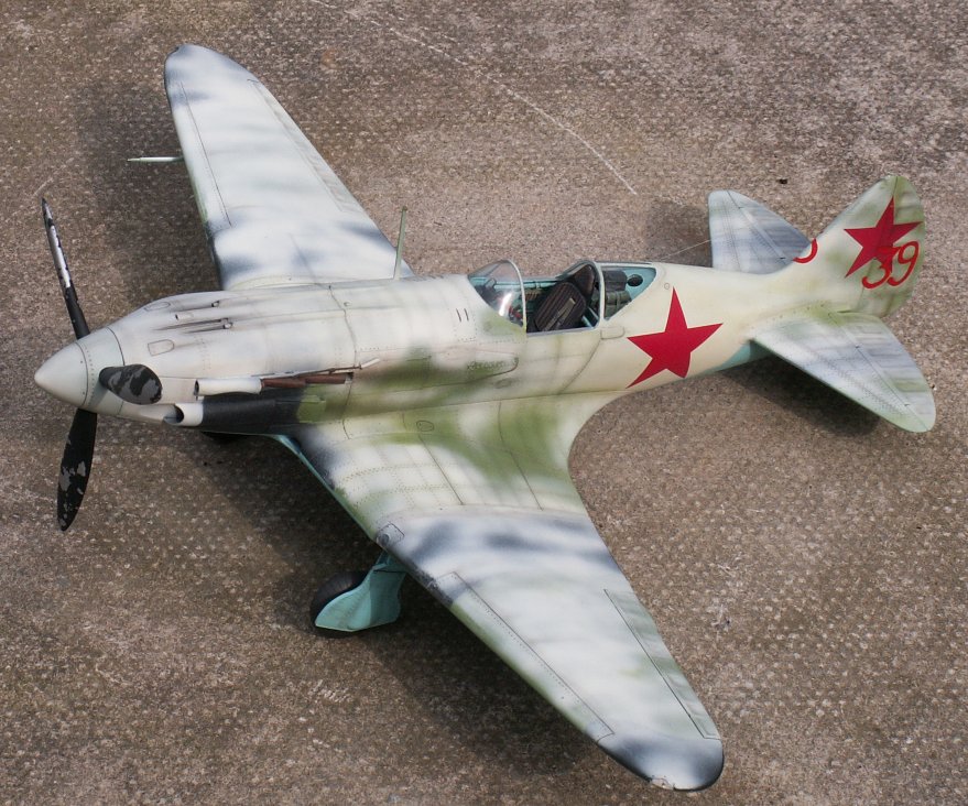
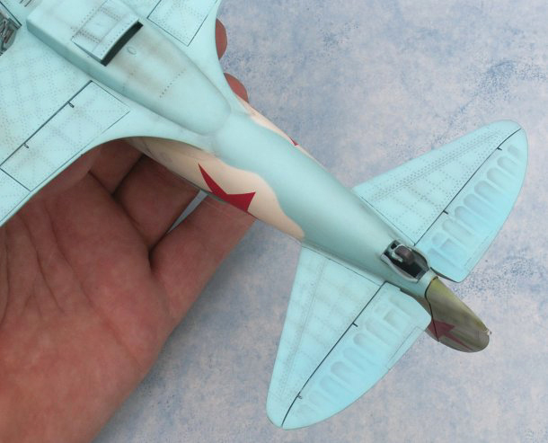
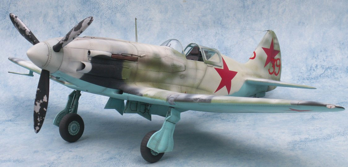
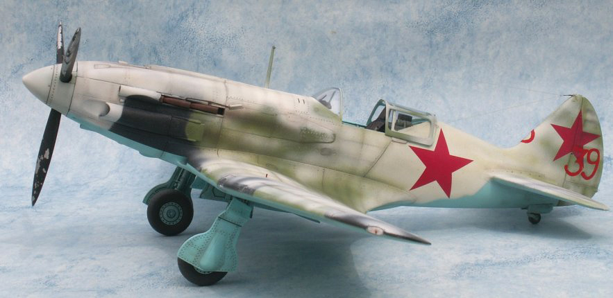
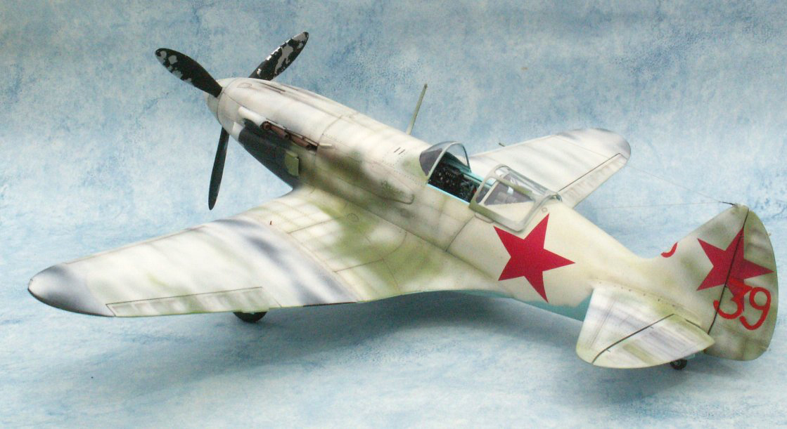
[Ed. Note: Peter has chosen to model MiG-3 "Red 39" from the infamous 120 IAP line-up photograph. See profile below.]
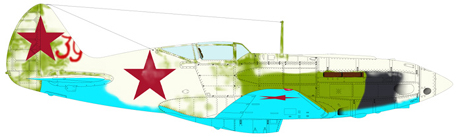
Starboard side view of Red 39, 120 IAP, at Moscow
Update 22 March 2005
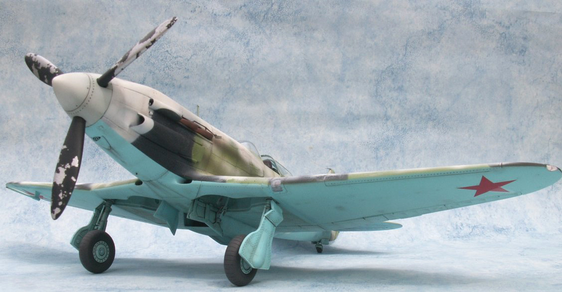
Work continues slowly , I am now approaching the end of the weathering stage, decals have been applied and my very good friend Bob Partridge applied by hand using oil paints the red 39s to the rear fin and rudder for which I am truely thankful, when this is totally dry in about 2 weeks I will apply a little more weathering to the underside and then overcoat with matt finishe before final assembly.
I must state that my photos do not do the model justice, I might see
if a fellow club member at the Avon IPMS can do better.
 |
 |
 |
 |
 |
 |
 |
 |
 |
 |
||
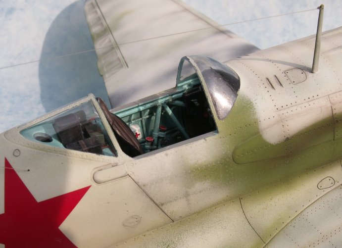
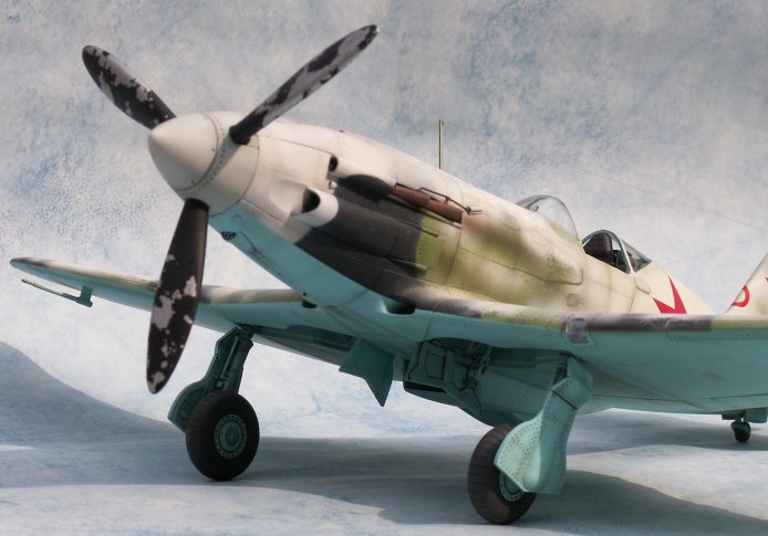
Update 28 April 2005
Today's update is a bit visual, really. After 14 months in construction, Peter is nearly done ("..all that is still required is to fix the sliding canopy hood and place the landing gear down indicators into the wing..."). Thus, we present a gallery of the nearly completed model. A larger posting will follow, we think with Peter's final thoughts and comments on an awfully big project....
 ...
... ...
...
 ...
... ...
...
 ...
... ...
...
 ...
... ...
...
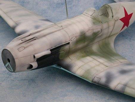
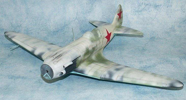
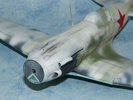
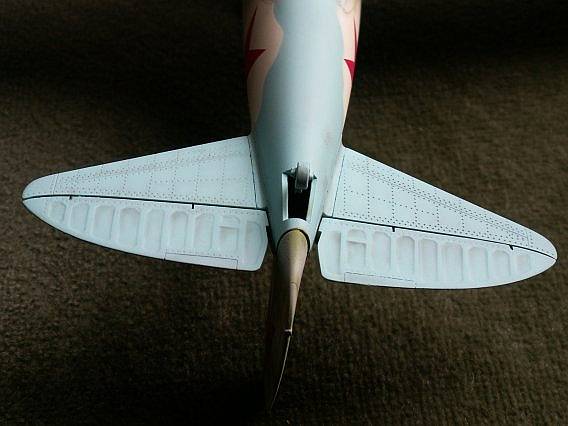
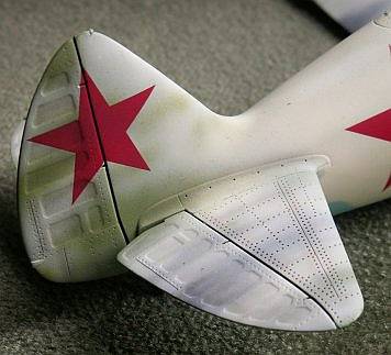
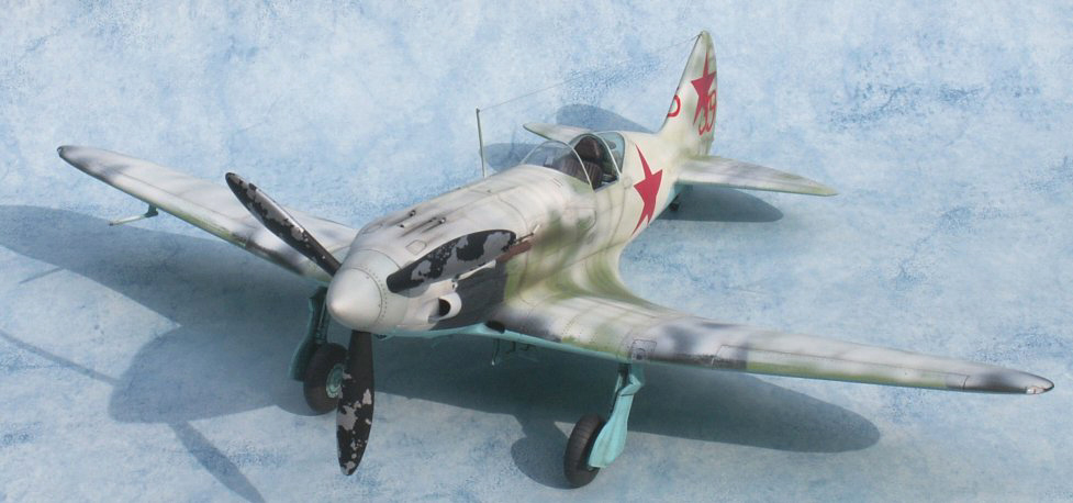
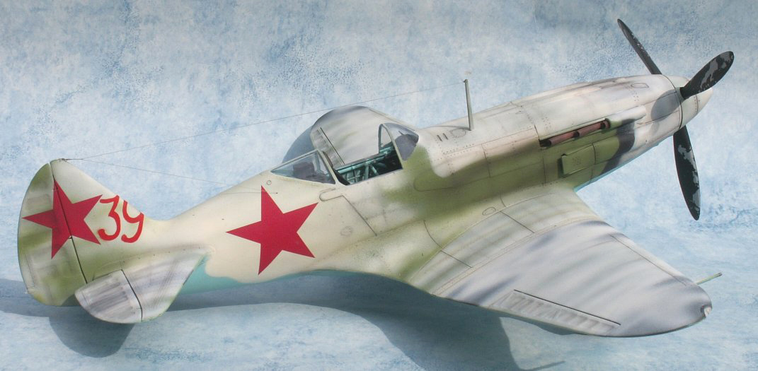
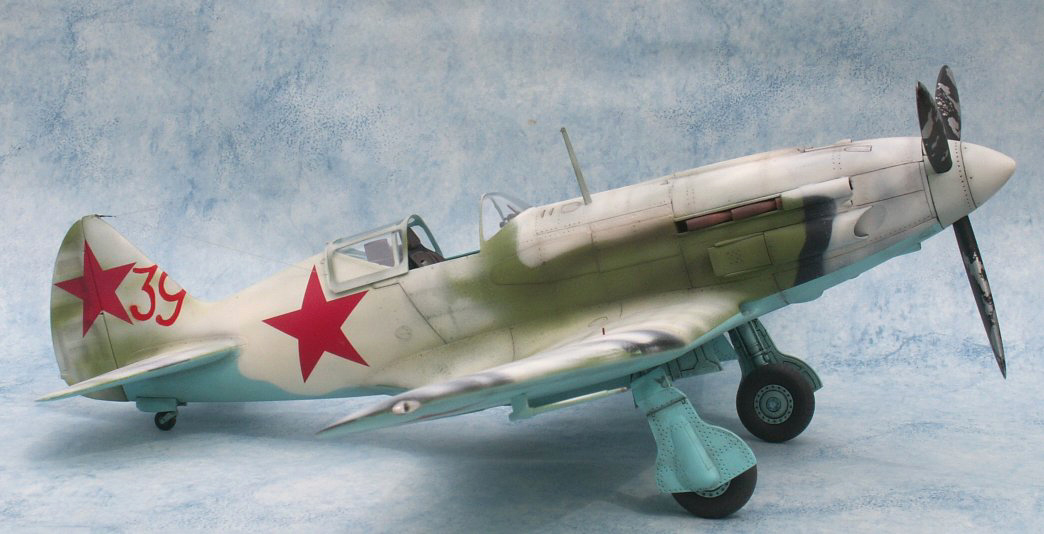
Conclusion and Final Thoughts, May 2005
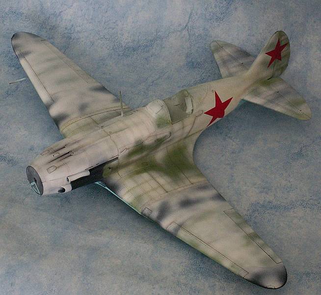
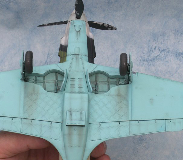
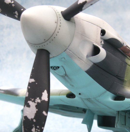
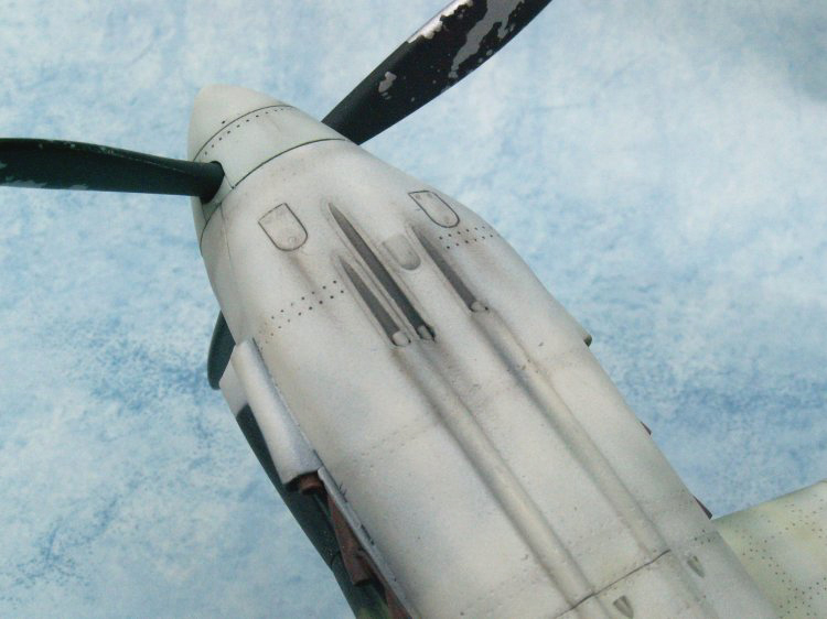
The following are images of the completed model.
 ....
.... ....
....
 ....
.... ....
....
 ....
.... ....
....
 ....
.... ....
....
 ........
Thats it folks-- game over. I hope you have enjoyed it as much as I have. I am not one to be normally stuck for words (as any one who knows me will testify), but I really don`t have a clue what to say at this point so please forgive me if I ramble on....
I would recommend the Trumpeter 1/32 scale MIG-3 to any one, even if they have not built a kit in this scale before. The beauty of this model is that the finished product does not require a seperate room to display it in, and when built it is quite small even if compared to 1/48scale bombers. The kit itself goes together very well in my opinion, requiring very little filler and presents very few problems. Modellers of all ages and skill levels should be able to produce a kit that they are proud of. The only real problem area that springs to mind was fitting the leading edge slats in the closed position (as they should be if the aircraft is on the ground); however if you are not too concerned about having them open, they fit perfectly.
14 months spent on making a model might seem like a long time, but other things have from time to time attracted my attention. I have completed three other models during that time, all three being models of Belgian aircraft-- a Gladiator, F84 and a F-104.
The MiG build has been interesting for me in so much as it allowed
(or forced) me to once again pick up and read/study techinical drawings.
One thing I noticed quite early on is that no two sets of MiG-3 plans
agree with each other. In fact, if you take your time and compare the drawings
to actual photos you will see that most are totally incorrect. The best
drawings I found were supplied by Erik Pilawskii and came in a booklet
whose text was all in Russian and also covered the LaGG-3 and La-5. The
other good point, as far as I am concerned, is that I re-discovered the
joy of scratch building such a large component as the cockpit. I normally
only scratch build detail parts with most of my builds. I do hope that
I have convinced a few of you reading this build article over the last
14 months to have a go yourself at scratch building some component or sub
assembly- believe me, if I can do it so can YOU. I also hope that you have
enjoyed watching this model come together.
Erik informs me that other modellers are waiting to join the "Work Bench" team. I do hope that this happens, not because it was my idea, but due to the fact that there are a large number of modellers out there with a great deal of skills and the "Work Bench" provides a forum for them to pass these on to others. The original idea of the "Work Bench" was for me to build the cockpit and finish at that point, but the idea grew. If you want to do a "Work Bench" article on just one specific area of your model or model building technique, then I am sure Matt/Erik will be happy to post it. My friend Bob Partridge is building a cockpit from scratch for his Trupeter P-40. Ok, the model will not be finished in VVS markings, but those of us who have this 1/32 scale kit and intend to complete it as a VVS aircraft could benifit from his work. Thus, although he don`t know it yet, he is about to do a "Work Bench" article....
Thanks for being with me on our trip
Special thanks to
Erik Pilawskii
Aleksandar Sekularac
Bob Partridge
Sean Walsh
Ira
Massimo Tessitori
I would be glad to receive any comments good or bad, I am happy to assist
or answer any
questions you may have (assuming I can).
Peter Vill