ICM 1/72nd Tupolev TB-3
by Michael Kendix
ICM 1/72nd Tupolev TB-3by Michael Kendix |
|
An in-box review of this kit and a brief background on the TB-3 appeared in the October 2000 edition of Internet Modeler.
My relationship with this model began a long time ago. I bought this kit and
the aftermarket photoetch set from Eduard several years ago–each cost
about $20. At various intervals I would open the box, gaze at the large stack
of green sprues and the instructions, and then replace the box lid. For a fairly
long time, I never saw this kit built but gradually I began to see one or two
appear at model shows, and the occasional one on the web. One thing that struck
me as an avid contest modeler and judge at said events, is that none of these
models was ever likely to win me anything at IPMS events in the United States
– it appeared the build was just too difficult and I could never build
the kit without making too many minor mistakes. However, at some point I saw
Aleksandar 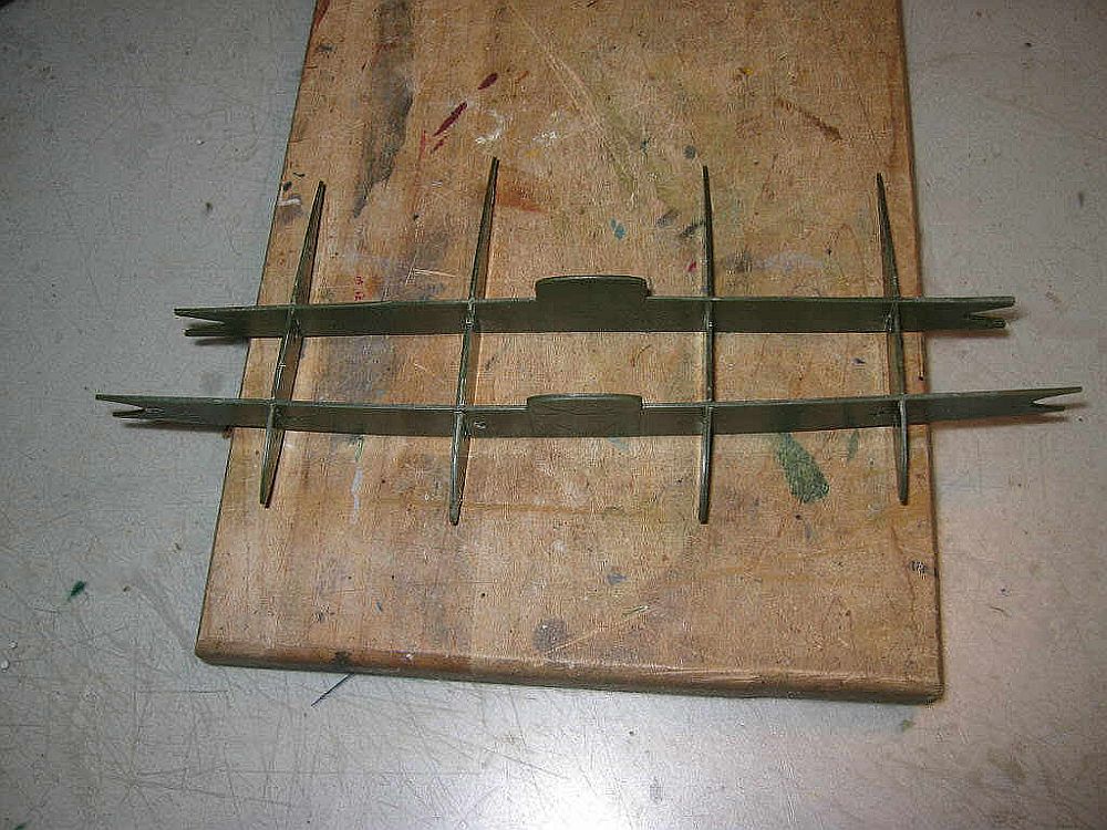 Šekularac’s
amazing rendition of this kit on this
web site. Of course, he had gone the whole hog: not only had he used the
Eduard aftermarket set but he had added a couple of I-16 type 5’s from
kits made by A-Model as parasites under the wing surfaces to create a Zveno.
In fact, ICM does provide a Zveno version of the TB-3 but the I-16’s in
that kit are Type 24’s, which is not really correct for this TB-3. Of
course, this is understandable since ICM makes Type 24’s and not Type
5’s. However, I digress, the more I looked at this model, the more I thought
about building it since the alternative was to let it sit in the box forever,
plus I had to justify forking out $20 for the Eduard aftermarket set.
Šekularac’s
amazing rendition of this kit on this
web site. Of course, he had gone the whole hog: not only had he used the
Eduard aftermarket set but he had added a couple of I-16 type 5’s from
kits made by A-Model as parasites under the wing surfaces to create a Zveno.
In fact, ICM does provide a Zveno version of the TB-3 but the I-16’s in
that kit are Type 24’s, which is not really correct for this TB-3. Of
course, this is understandable since ICM makes Type 24’s and not Type
5’s. However, I digress, the more I looked at this model, the more I thought
about building it since the alternative was to let it sit in the box forever,
plus I had to justify forking out $20 for the Eduard aftermarket set.
 When
I started building this model, I had to make some decisions about certain issues.
First, how much extra detail/trouble was I prepared to include here? Second,
where am I going to start? I decided that the wing was going to be the trickiest
part, and if that didn’t go together well, there would be no point continuing,
so back in March 2006, I started assembling the wing. I cannot over-emphasize
how much I relied on Aleksandar Šekularac’s pictures and description
on the VVS web site because without that, I would have been dead in the water,
so to speak.
When
I started building this model, I had to make some decisions about certain issues.
First, how much extra detail/trouble was I prepared to include here? Second,
where am I going to start? I decided that the wing was going to be the trickiest
part, and if that didn’t go together well, there would be no point continuing,
so back in March 2006, I started assembling the wing. I cannot over-emphasize
how much I relied on Aleksandar Šekularac’s pictures and description
on the VVS web site because without that, I would have been dead in the water,
so to speak.
 The
wing has about 25 pieces for both the port and starboard sides. I decided I
wasn’t going to do the “Trashcan” gun emplacements on the
underside of the wing so I blocked those off. The multipart wing contains all
the spars and interior components that you would find in the real thing but
of course, they don’t show once the thing is assembled. The skin too is
in multiple pieces–more than 10 in total, I think. Everything has to be
dry-fitted really carefully because as you can obviously see, the entire skin
of the aircraft is corrugated, which precludes any kind of regular seam filling
and sanding. I managed to fit the various spars together and I glued them to
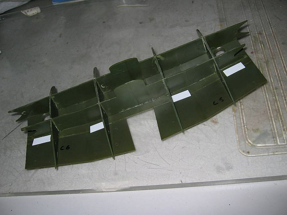
the underside skin. Once that was dry I attempted to add the upper skin of the
wing but it didn’t fit! A panicked email to Aleksandar Šekularac
and a rapid response revealed that this was the case for him too and that I
should expect plenty of fit problems. I pulled out my trusty Dremel tool, flipped
the speed to 10,000 RPM and proceeded to sand and melt off a goodly portion
of the spar structure, pausing at various intervals to test to see if the top
skin would fit. At this point I recall that the plastic was veritably flying
off the spars and burning my arms as bits of the melting residue
The
wing has about 25 pieces for both the port and starboard sides. I decided I
wasn’t going to do the “Trashcan” gun emplacements on the
underside of the wing so I blocked those off. The multipart wing contains all
the spars and interior components that you would find in the real thing but
of course, they don’t show once the thing is assembled. The skin too is
in multiple pieces–more than 10 in total, I think. Everything has to be
dry-fitted really carefully because as you can obviously see, the entire skin
of the aircraft is corrugated, which precludes any kind of regular seam filling
and sanding. I managed to fit the various spars together and I glued them to
the underside skin. Once that was dry I attempted to add the upper skin of the
wing but it didn’t fit! A panicked email to Aleksandar Šekularac
and a rapid response revealed that this was the case for him too and that I
should expect plenty of fit problems. I pulled out my trusty Dremel tool, flipped
the speed to 10,000 RPM and proceeded to sand and melt off a goodly portion
of the spar structure, pausing at various intervals to test to see if the top
skin would fit. At this point I recall that the plastic was veritably flying
off the spars and burning my arms as bits of the melting residue  landed
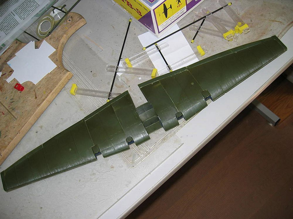
on my skin. After an evening of this and with the help of some wonderful adjustable
clamps I had bought at the 2005 US Nationals, I managed to get the wing together.
Prior to gluing everything down, however, I sprayed the interior of the wing
black because the photo etch engine access wing cut-out piece will allow you
to see inside the wing just a little. In order to see how things had gone, I
sprayed this huge subassembly with Mr. Surfacer. It didn’t look terrible
but there were definitely some small gaps and a few glue spots. I couldn’t
really think how to get rid of these because of the corrugated surfaces so I
put it into a plastic bin container and left it there.
landed
on my skin. After an evening of this and with the help of some wonderful adjustable
clamps I had bought at the 2005 US Nationals, I managed to get the wing together.
Prior to gluing everything down, however, I sprayed the interior of the wing
black because the photo etch engine access wing cut-out piece will allow you
to see inside the wing just a little. In order to see how things had gone, I
sprayed this huge subassembly with Mr. Surfacer. It didn’t look terrible
but there were definitely some small gaps and a few glue spots. I couldn’t
really think how to get rid of these because of the corrugated surfaces so I
put it into a plastic bin container and left it there.
 I
don’t know what happened exactly but when I pulled it out of the bin about
three months later, it didn’t look so bad. During that time I had polished
off two other kits and I was ready to start back again on the TB-3.
I
don’t know what happened exactly but when I pulled it out of the bin about
three months later, it didn’t look so bad. During that time I had polished
off two other kits and I was ready to start back again on the TB-3.
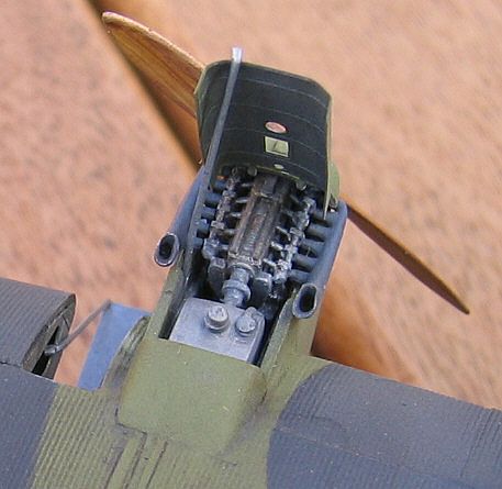
One of the less interesting aspects about large aircraft models is that there
is multiples of everything and in this case, there are four engines, so the
process of construction is somewhat repetitious. Please don’t misunderstand
me, the kit’s engines are excellent, especially considering that almost
nothing of them can be seen once the engine cover is glued on. To cut through
this potential boredom, I resorted to the Eduard photoetch set, which contains
some nice detail for the rear section of each engine and one engine cover that
can be raised to show the engine detail for one of the engines. While the engine
detail is more than sufficient when the cover is closed, this is not the case
when the cover is in the open position. I rectified this by scratch building
an engine to go into 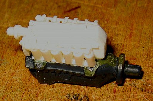 one
of the engine compartments, relying heavily on Mr. Šekularac’s build
and some references on the web that he showed me. I used the kit’s engine
block as a basis and added the various cylinder parts and other features using
pieces of plastic rod and card, and I made the tank behind the engine using
the same. One problem with the photo etch engine cover is that the configuration
of its holes is different to those of the kit engine covers. In order to match
them all up I followed Mr. Šekularac’s advice and “moved”
the kit’s holes. Part of this little open-engine vignette entailed installing
the photoetch for the access step next to said engine. In order to do this,
I had to cut out the appropriate section of the wing’s leading edge and
insert the photoetch pieces. However, at this point I only installed the wing
piece, not the hanging-down step itself, which would have broken off too easily
during the building process. The engines themselves are nice enough but assembling
their housings was not straightforward. Each engine housing has six outer pieces,
all of which are butt joined and must be carefully prodded in place. Once glued,
various gaps were apparent and other panel lines were lost. It took several
sequences of filling, spraying with primer and re-scribing to bring these components
up to an acceptable standard. Once this was completed, I
one
of the engine compartments, relying heavily on Mr. Šekularac’s build
and some references on the web that he showed me. I used the kit’s engine
block as a basis and added the various cylinder parts and other features using
pieces of plastic rod and card, and I made the tank behind the engine using
the same. One problem with the photo etch engine cover is that the configuration
of its holes is different to those of the kit engine covers. In order to match
them all up I followed Mr. Šekularac’s advice and “moved”
the kit’s holes. Part of this little open-engine vignette entailed installing
the photoetch for the access step next to said engine. In order to do this,
I had to cut out the appropriate section of the wing’s leading edge and
insert the photoetch pieces. However, at this point I only installed the wing
piece, not the hanging-down step itself, which would have broken off too easily
during the building process. The engines themselves are nice enough but assembling
their housings was not straightforward. Each engine housing has six outer pieces,
all of which are butt joined and must be carefully prodded in place. Once glued,
various gaps were apparent and other panel lines were lost. It took several
sequences of filling, spraying with primer and re-scribing to bring these components
up to an acceptable standard. Once this was completed, I 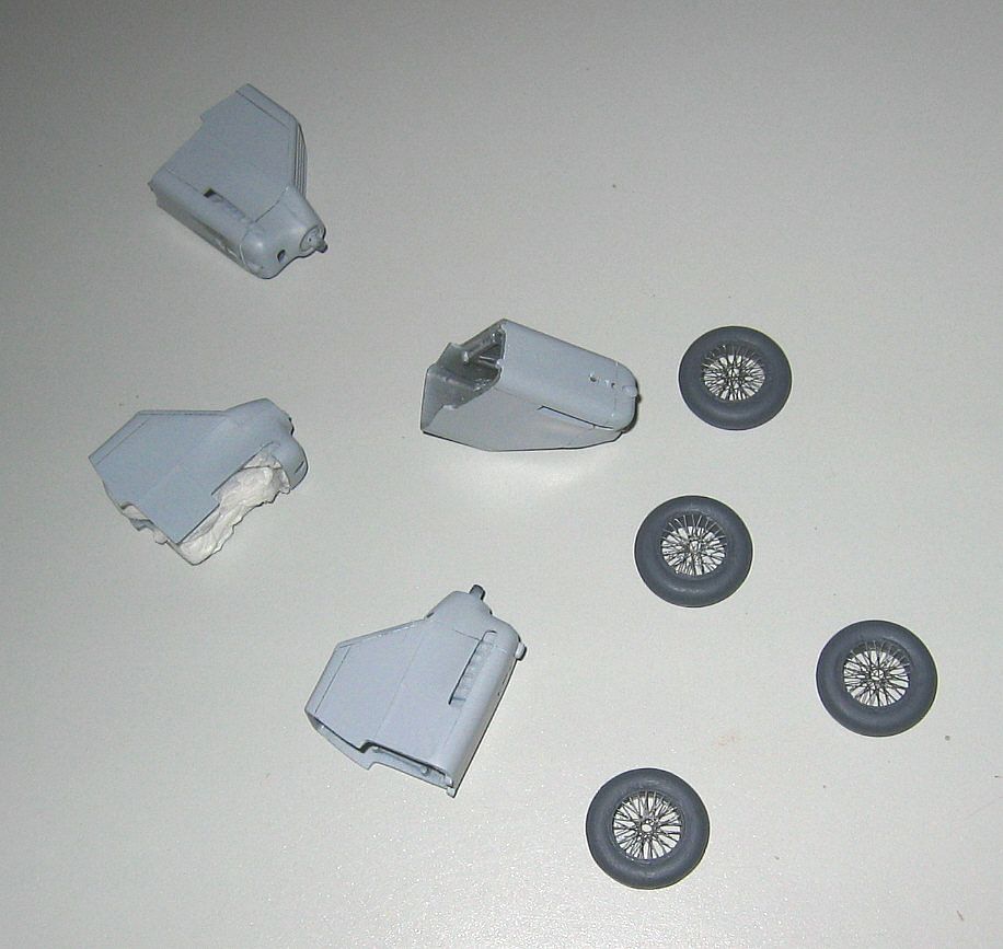 glued
the engines into their positions in the wing. Once again, there were significant
fit problems but one has to recognize that such problems are an inevitable price
for the way the kit is constructed: it’s almost impossible to align the
pieces during construction so that such gaps will not occur. As mentioned above,
you cannot simply fill the gaps and sand the area flush because the entire wing
and fuselage surfaces are corrugated. In order to deal with this I followed
the advice of Mr. Šekularac and used thin strips of plastic, which I glued
into the gaps. Once again, there were several round of filling, prodding and
primer spraying.
glued
the engines into their positions in the wing. Once again, there were significant
fit problems but one has to recognize that such problems are an inevitable price
for the way the kit is constructed: it’s almost impossible to align the
pieces during construction so that such gaps will not occur. As mentioned above,
you cannot simply fill the gaps and sand the area flush because the entire wing
and fuselage surfaces are corrugated. In order to deal with this I followed
the advice of Mr. Šekularac and used thin strips of plastic, which I glued
into the gaps. Once again, there were several round of filling, prodding and
primer spraying.
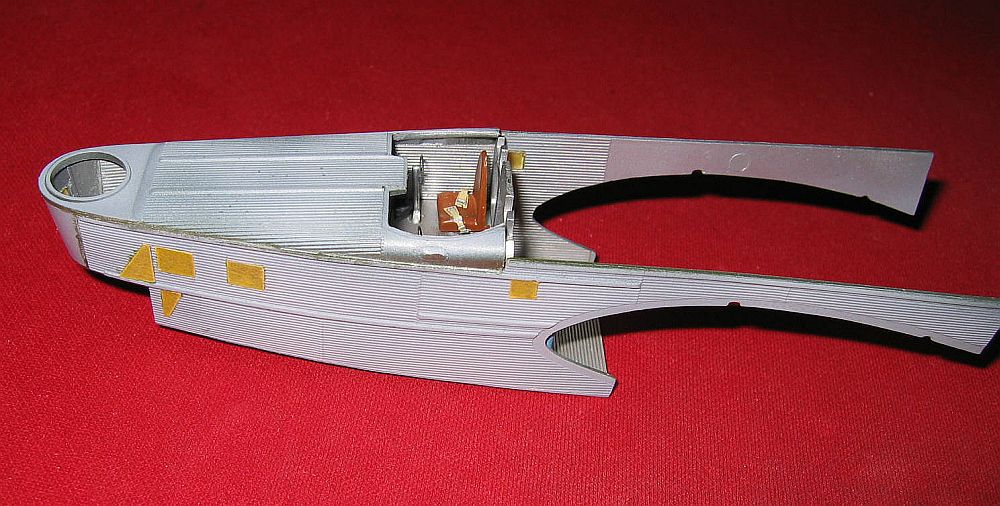
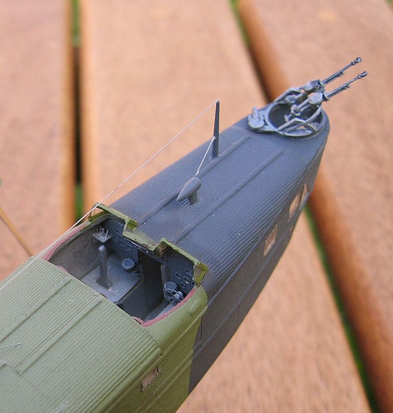
The construction of the fuselage was the most interesting and satisfying part
of this build. The detail 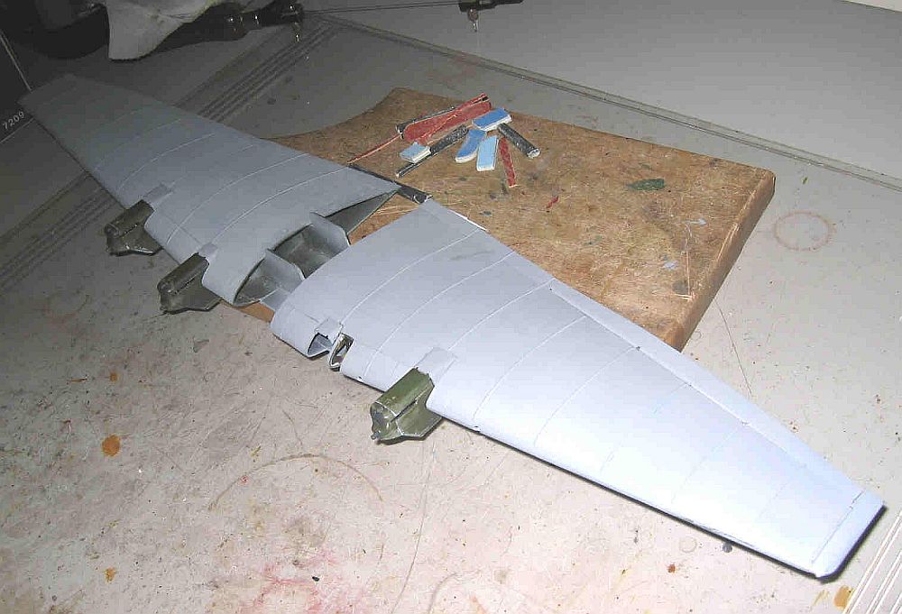 is
incredible even without the aftermarket photoetch but with it, you can really
dress up the main cockpit area, and this is really the only interior area that
can be seen once the model is finished. The photoetch seatbelts, instrument
panel and other main cockpit components will all be in plain view so it’s
great if you can add these various extra pieces. A great deal of detail is in
the forward section underneath the nose gunner’s position, however, even
though there are a lot of clear parts surrounding this area, little of the inside
can be seen once the fuselage is assembled. The fuselage components, including
the outer skin and all nine of the bulkheads went together quite well.
is
incredible even without the aftermarket photoetch but with it, you can really
dress up the main cockpit area, and this is really the only interior area that
can be seen once the model is finished. The photoetch seatbelts, instrument
panel and other main cockpit components will all be in plain view so it’s
great if you can add these various extra pieces. A great deal of detail is in
the forward section underneath the nose gunner’s position, however, even
though there are a lot of clear parts surrounding this area, little of the inside
can be seen once the fuselage is assembled. The fuselage components, including
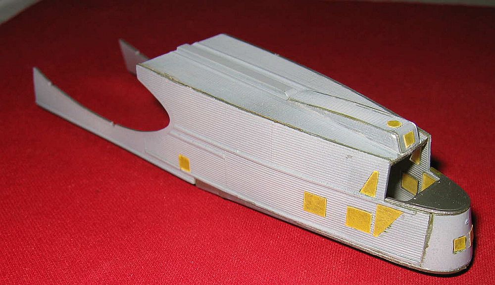
the outer skin and all nine of the bulkheads went together quite well. 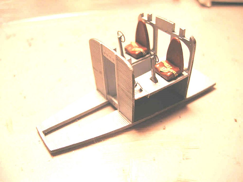 Naturally,
I had to use extra care dry fitting these pieces but compared to the wing, this
part of the build went quite smoothly. The main problem I faced was gluing the
straight fuselage sides to the curved fuselage base. In order to do this I used
those clamps again and glued the parts together in stages. Starting with the
forward area, I glued that section, clamped it and waited for that to set-up.
I repeated this sequence working my way gradually to the rear. At this point
you also
Naturally,
I had to use extra care dry fitting these pieces but compared to the wing, this
part of the build went quite smoothly. The main problem I faced was gluing the
straight fuselage sides to the curved fuselage base. In order to do this I used
those clamps again and glued the parts together in stages. Starting with the
forward area, I glued that section, clamped it and waited for that to set-up.
I repeated this sequence working my way gradually to the rear. At this point
you also  have
to assemble and glue in the front section of the tail and once again, care is
required in assembling this part because it is not completely obvious exactly
how the pieces are to fit with each other. One problem with the forward part
of the horizontal tail was the lack of any decent attachment point, which meant
this thing kept on coming unglued.
have
to assemble and glue in the front section of the tail and once again, care is
required in assembling this part because it is not completely obvious exactly
how the pieces are to fit with each other. One problem with the forward part
of the horizontal tail was the lack of any decent attachment point, which meant
this thing kept on coming unglued.
Before adding the fuselage top, I glued in the clear parts. Unfortunately, every single one was too big, which gave me a choice: either widen the window frames or reduce the size of the clear parts. I chose the latter, frequently dry-fitting the piece each time I sanded it a little. I glued these in with Elmer’s white glue so as not to make a mess of them and I was fortunate that they all held up to the stress of masking them and painting.
 |
 |
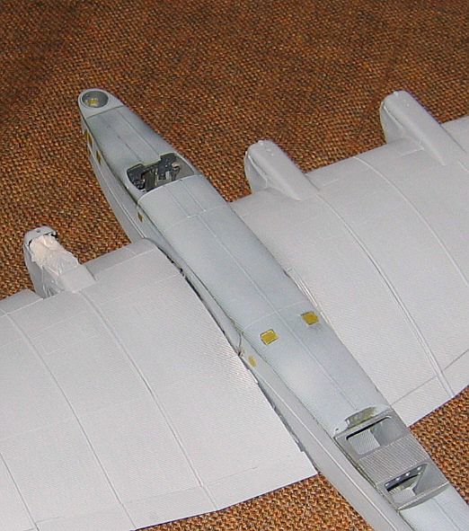
Once the fuselage was completed, I glued it onto the wing, which was far from
straightforward. The over-engineered construction of the wing and fuselage components
makes it easy to allow a slight asymmetry to creep in, which lead to significant
gaps at the wing-fuselage joins. Again, I glued in slivers of plastic to fill
these gaps, and the process of filling, sanding a little then spraying with
primer 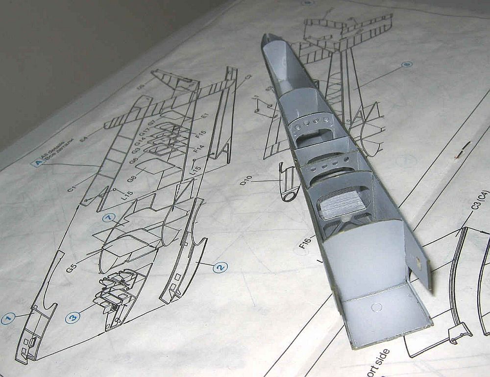 to
ensure that all the gaps were filled properly, took some time. Finally, I added
the large clear part that goes on the front of the fuselage. This clear part
fit well but I was uncertain whether the underside of this contained windows
or not and I decided it did not, however, further investigation has lead me
to believe I made a mistake here. Although it would have meant that people could
actually walk out over and onto the glass windows, I think that’s how
it was.
to
ensure that all the gaps were filled properly, took some time. Finally, I added
the large clear part that goes on the front of the fuselage. This clear part
fit well but I was uncertain whether the underside of this contained windows
or not and I decided it did not, however, further investigation has lead me
to believe I made a mistake here. Although it would have meant that people could
actually walk out over and onto the glass windows, I think that’s how
it was.
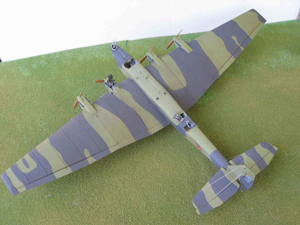
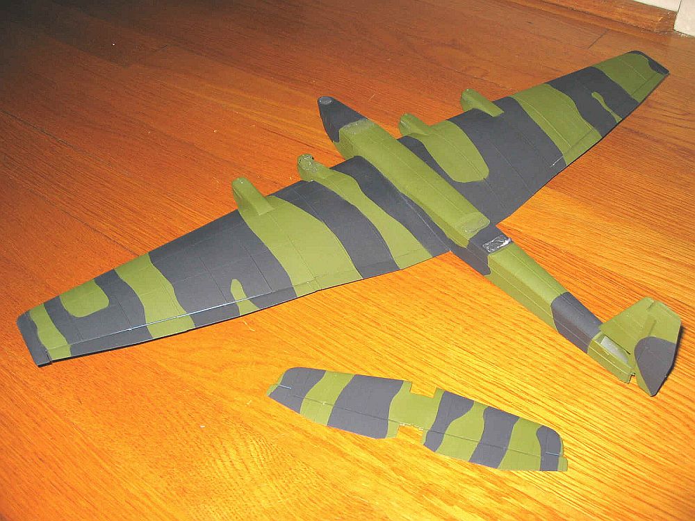
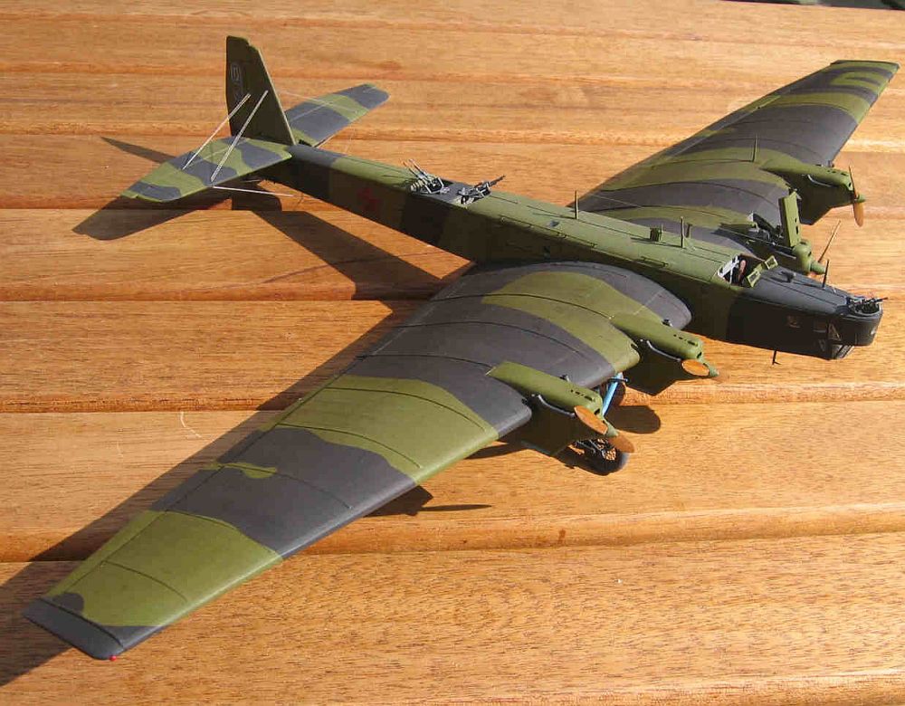
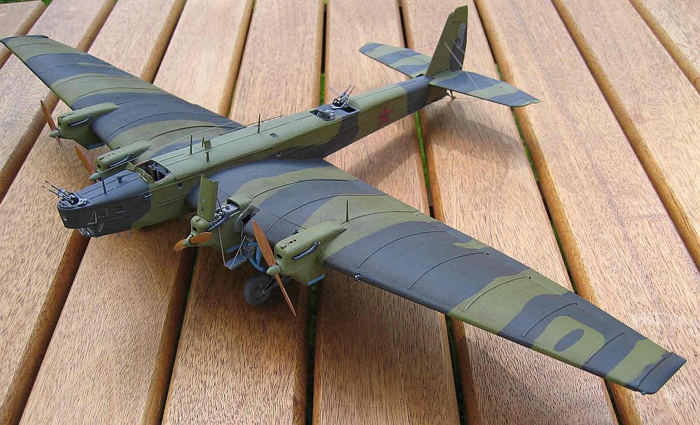
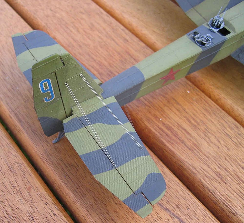
 After
much consideration, I decided to paint the model as “Blue 9”: a
scheme that comes with the kit–250 APDD, summer, 1942–a somewhat
later version than some of the other kit schemes. The upper surfaces are AII
black and AII green and the lower surface is AII blue. There is some uncertainty
as to whether the red stars were outlined in black and whether they appeared
on the wing’s upper surface. I chose to do plain red stars and omit the
upper wing surface stars – more on the decals later.
After
much consideration, I decided to paint the model as “Blue 9”: a
scheme that comes with the kit–250 APDD, summer, 1942–a somewhat
later version than some of the other kit schemes. The upper surfaces are AII
black and AII green and the lower surface is AII blue. There is some uncertainty
as to whether the red stars were outlined in black and whether they appeared
on the wing’s upper surface. I chose to do plain red stars and omit the
upper wing surface stars – more on the decals later.
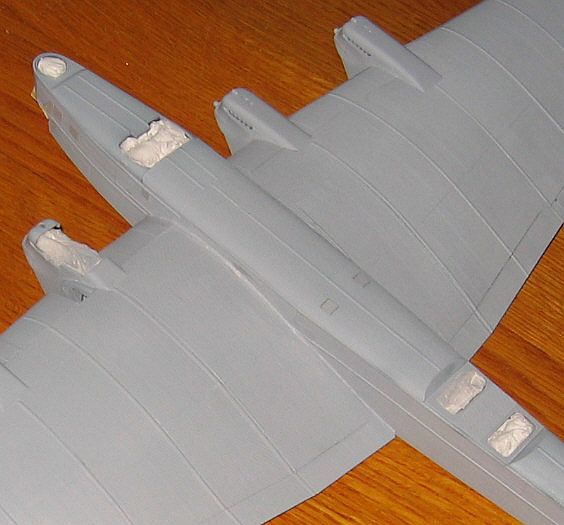
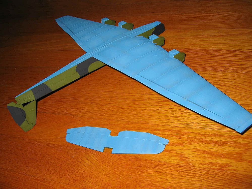
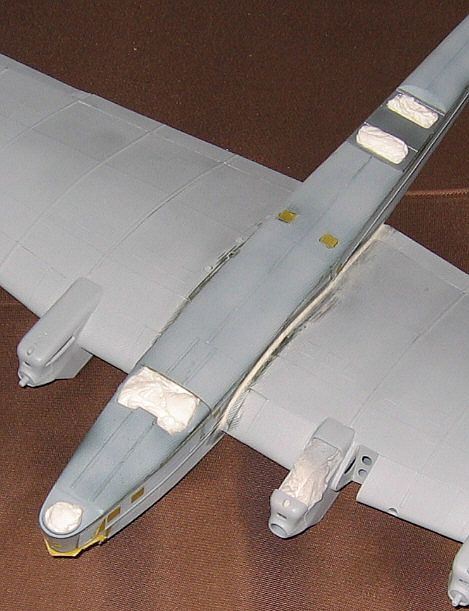 After
stuffing the gun emplacements and cockpit areas with tissue paper, I painted
the underside using Testors flat blue, which I lightened with a little white.
At this phase, it looked a little bright but I eventually toned it done with
an oil wash later in the building process. Once this had been done, I masked
off the blue and sprayed the black for which I used straight black lightened
slightly with a little white. At this point, the model looked like a sort of
night fighter. Once the black was dry, I masked and sprayed the green for which
I used Model Masters US Interior Green. Despite the corrugations, masking with
3M blue masking tape went well, and I only needed to do a few touch-ups.
After
stuffing the gun emplacements and cockpit areas with tissue paper, I painted
the underside using Testors flat blue, which I lightened with a little white.
At this phase, it looked a little bright but I eventually toned it done with
an oil wash later in the building process. Once this had been done, I masked
off the blue and sprayed the black for which I used straight black lightened
slightly with a little white. At this point, the model looked like a sort of
night fighter. Once the black was dry, I masked and sprayed the green for which
I used Model Masters US Interior Green. Despite the corrugations, masking with
3M blue masking tape went well, and I only needed to do a few touch-ups.
 The
decals for this kit are not that great, which contributed to my decision to
not bother with the upper side wing decals. I put one of the star decals in
a bowl of water to test its structural integrity and it just about disintegrated.
I took some Microscale Liquid Decal Film and brushed a couple of coats carefully
over the decals I planned to use. I trimmed the edges of the decals as much
as I could and brushed on a few coats of Future to prepare the surface for the
decals. Those on the underside went on fairly well but the fuselage stars suffered
from some discoloration, which I was able to disguise in part when I gave the
model an oil wash. The “9” decals on the tail went on relatively
easily though some crumbling of their white surround meant I had to touch them
up with a little paint.
The
decals for this kit are not that great, which contributed to my decision to
not bother with the upper side wing decals. I put one of the star decals in
a bowl of water to test its structural integrity and it just about disintegrated.
I took some Microscale Liquid Decal Film and brushed a couple of coats carefully
over the decals I planned to use. I trimmed the edges of the decals as much
as I could and brushed on a few coats of Future to prepare the surface for the
decals. Those on the underside went on fairly well but the fuselage stars suffered
from some discoloration, which I was able to disguise in part when I gave the
model an oil wash. The “9” decals on the tail went on relatively
easily though some crumbling of their white surround meant I had to touch them
up with a little paint.
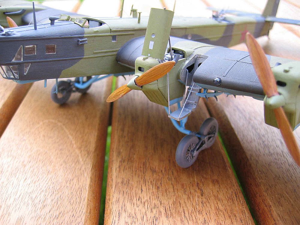
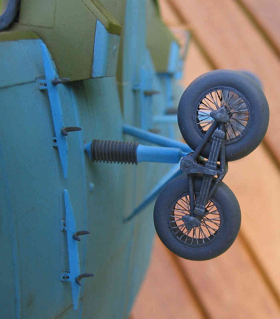
 The
bits and pieces that one tacks onto this model are excellent. The wheels and
bogies are excellent–each side is a little kit in itself. My research
showed that this version of the TB-3 had wheels with spokes. Using the method
suggested by Aleksandar Šekularac, I glued together the wheel halves, drilled
out the centers, filled the tires with Squadron White Putty and glued on the
wheel spokes from the Eduard photo etch set. The landing gear struts presented
some problems. I had to replace some of the ends of the struts in order for
the parts to sit right. I also had to replace the piece that goes through the
wheel subassembly with brass tubing so it didn’t bend and make the wheels
splay outward.
The
bits and pieces that one tacks onto this model are excellent. The wheels and
bogies are excellent–each side is a little kit in itself. My research
showed that this version of the TB-3 had wheels with spokes. Using the method
suggested by Aleksandar Šekularac, I glued together the wheel halves, drilled
out the centers, filled the tires with Squadron White Putty and glued on the
wheel spokes from the Eduard photo etch set. The landing gear struts presented
some problems. I had to replace some of the ends of the struts in order for
the parts to sit right. I also had to replace the piece that goes through the
wheel subassembly with brass tubing so it didn’t bend and make the wheels
splay outward.
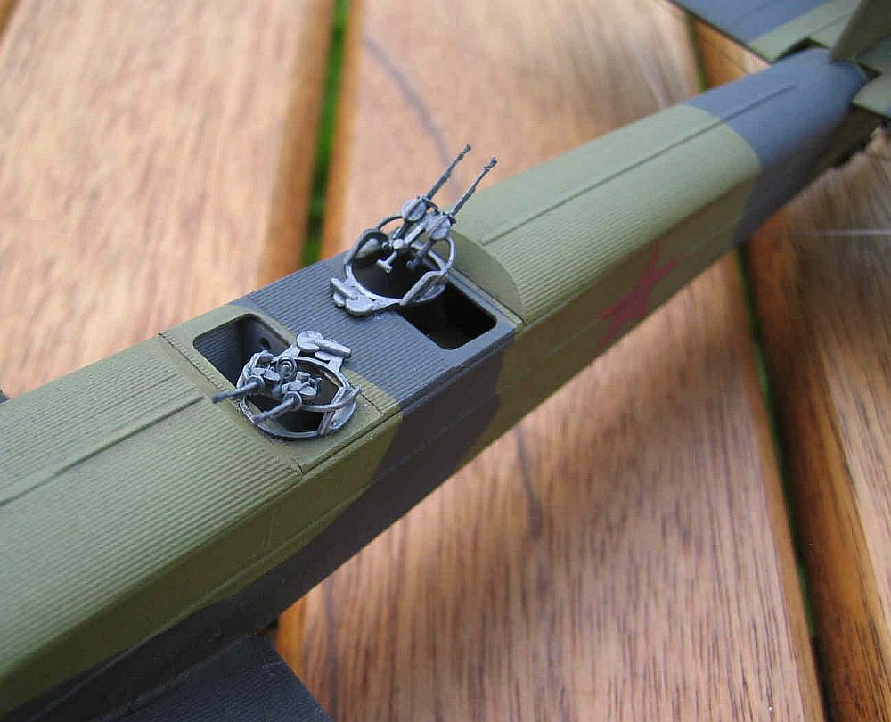
 I
used the photo etch set for the open engine cover and the engine maintenance
access step. I glued on the bomb racks but it was clear that the bombs would
have interfered with the engine access step so I left the bombs off. The photo
etch set also provides a number of replacement pieces for the guns and gun mounts,
however, I simply could not get these together so I used only the gun sight.
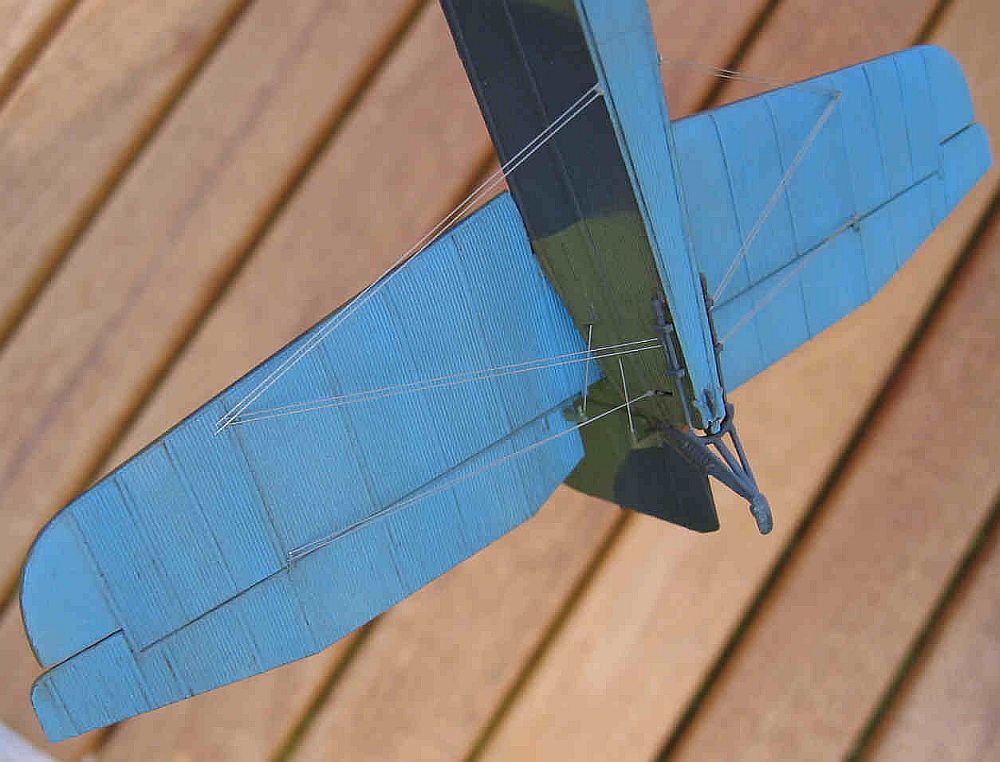
I created a wood grain appearance for the propellers by taking burnt umber and
dark brown gouache water paints and swiping them onto the surface with a Q-tip.
I then sprayed them with Tamiya clear yellow and finished the surface with a
coat of Future floor polish. The propeller blades have metal edges that I painted
with Testors metallic brass paint. I hollowed out the engines’ exhausts
with a number 11 blade on my Exacto knife and a drill, and added the rigging
on the tail and the antennae using 0.005-inch steel straight wire from Smallparts.
Inc. I gave the entire model an oil wash with burnt umber oil paint thinned
with Turpenoid and then some light weathering with pastel chalks for the stains
behind the engines’ exhausts.
I
used the photo etch set for the open engine cover and the engine maintenance
access step. I glued on the bomb racks but it was clear that the bombs would
have interfered with the engine access step so I left the bombs off. The photo
etch set also provides a number of replacement pieces for the guns and gun mounts,
however, I simply could not get these together so I used only the gun sight.
I created a wood grain appearance for the propellers by taking burnt umber and
dark brown gouache water paints and swiping them onto the surface with a Q-tip.
I then sprayed them with Tamiya clear yellow and finished the surface with a
coat of Future floor polish. The propeller blades have metal edges that I painted
with Testors metallic brass paint. I hollowed out the engines’ exhausts
with a number 11 blade on my Exacto knife and a drill, and added the rigging
on the tail and the antennae using 0.005-inch steel straight wire from Smallparts.
Inc. I gave the entire model an oil wash with burnt umber oil paint thinned
with Turpenoid and then some light weathering with pastel chalks for the stains
behind the engines’ exhausts.
I
have about 75 built models on my shelf including several vacuform models and
an Ilya Mourametz but this was the most difficult kit I have built. The key
to building it was perseverance and patience. It simply cannot be rushed without
it being ruined and even then ultra-care is required. I also had a lot of helpful
advice and as mentioned above, I could not have done it without being able to
follow the web build of Aleksandar Šekularac. My finished model is no contest
winner because it contains far too many blobs and scrapes but it is an extremely
impressive-looking model. I recommend it conditionally for those who really
must have one of these in their collection.
I would like to thank the following for their invaluable advice and help. In alphabetical order, I would like to thank Matt Bittner for his advice and general encouragement, Michael Lampros for references, Erik Pilawskii for advice and references, Aleksandar Šekularac for advice and his phenomenal build on the VVS web site, and various members of the VVS web site forum for their encouragement.
|
 |
 |
 |
 |
 |
 |
 |
 |
 |