| |
|||||
Yak-1, -3, -7, -9
On the Yak fighter, the number and position of the various fuel cells--and therefore, of course, their filler caps, etc.--is one of the key items used to sort the different versions one from another. In many references the exact placement of these filler caps is confused, and nowhere (that I am aware of) is there any suitable graphic representation of what they might look like.
These considerations have brought about this article,
hopefully the first of several such like it. In it, we will attempt to sort
out the various details of the Yak's wing fuel arrangements, the position of
the filler caps and gauges, and other details.
The Fuel Gauges
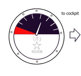
On the Yak fighter there are two notable pattern fuel gauges, an earlier and a later variety. The first unit was marked with gradation lines, only, and usually contained the logo of VIAM (All-Union Institute for Aviation Materials) printed on the instrument face in silver.
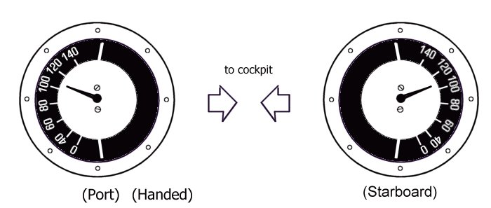
The later unit was considerably revised, and mounted quite differently. This gauge was placed with the face presented towards the cockpit, and the instrument faces were 'handed', so that the FULL indication was towards the leading edge on both sides of the wing.
The earlier instrument was seen from the beginning of the Yak fighter programme.
Examples of this gauge seem to be common on both the Yak-1 and -7 until some
time around the beginning of 1943 (or, in other words, close to the start of
Yak-9 manufacture). During the first half of 1943 the later pattern 'handed'
instrument seems to have supplanted the earlier type on most Yak fighters, including
the Yak-1 and -7. There is at least one photograph of an early Yak-9 at Stalingrad
with what seems to be the earlier instrument faces, and another showing one
of Maj. Shinkarenko's modified Yak-7Bs in February 1943 with the new types.
These two dates probably define, to a degree, the transition period (almost
certainly a gradual change, as was common in Soviet manufacture during the GPW)
between the different instrument types. There are, however, some indications
that the Yak-1, specifically, might have been produced with the earlier pattern
unit well into 1943; investigations on this point will continue.
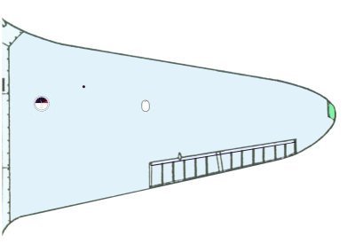
The Yak-1
The original Yak fighter wing, a 10.0 meter span unit with rounded wing tips, carried four fuel cells, two in each wing. Well, technically there were four cells--the pairs in each wing, in fact, functioned more like a two-part single fuel cell, and were filled by a single access hatch. This filler point was positioned well outboard, just about at the gap between the two cells. The fuel gauge, itself, was mounted abreast of the cockpit near the pilot's line of sight.
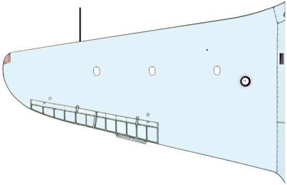
The Yak-7
The Yak-7, of course, featured the same 10.0 meter wing as the Yak-1 from which it was derived. However, the development of the -7 took a particularly different course to that of the Yak-1, and the disposition of the various wing gauges during the life of this machine were subtly changed.
The early examples of the Yak-7 featured the same fuel cell and filler point
arrangement as the Yak-1 wing, above. However, starting with the Yak-7B variant
the fuel gauge was repositioned further outboard and slightly farther forward,
probably to keep the instrument face from being damaged by empty cartridges
flying out of the ejection slot in the wing root.

This slightly modified arrangement seems to have lasted until the end of Yak-7
manufacture in 1944. The 'handed' type instruments were probably common on the
Yak-7 from 1943 onwards.
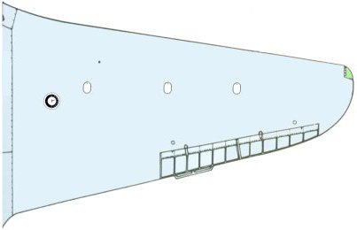
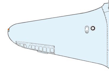
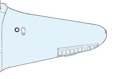
The Yak-9
The continuing development of the Yak-7 to provide greater and greater operating range resulted eventually in the Yak-7D and -DI prototypes, the latter of which entered production as the Yak-9. The -9 featured the new and revised tip arrangement on wings of 9.74 meter span. The result, in planform, is a rather 'blunted' shape, but one that is pleasing to the eye. The new wing featured a dural spar of very advanced design, and around this unit a number of fuel cells could be distributed to provide for a considerable increase in range.
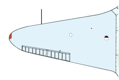
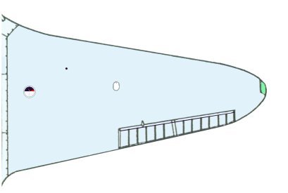
The original Yak-9 was completed with only one fuel cell in each wing, each
with a capacity of 220 liters. As a result, only one filler point was required,
this mounted in a position well inboard near the gauge.


A small number of early Yak-9s may have featured the earlier pattern fuel gauge,
but the vast majority of this type demonstrated the improved 'handed' type instruments.
This pattern was also common on the Yak-9T and -K models, but there is some
evidence that perhaps later models of the -9T might have featured the revised
Yak-9M fuel arrangement [see below].
In the Yak-9D, two additional fuel cells were added to the wings, bringing
the total to four. Consequently, two additional filler caps appeared, these
mounted near the outboard edge of the extra cells.


The extended long range Yak-9DD added yet two more cells, bringing the total
in the wing to six (with a total capacity of 845 liters). The extra outboard
cells also featured their own filler cap, as shown.
In fact, the disposition of the filler caps is quite logical when one takes
into account the arrangement of the fuel cells, themselves. The fuel cells in
the Yak-9/-D/-DD's wing were mounted according to the following diagram:
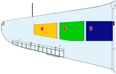
Thus, the Yak-9DD featured all three cells in each wing, whilst the -9D carried
only the inner two (green and blue), and the Yak-9/-9T/-9K only the innermost
cell (blue). This arrangement can be said to form the 'original pattern' Yak-9
fuel system, derived directly from the Yak-7D and -DI prototypes.
A revised fuel arrangement was developed for the Yak-9M model, however, this
variant sporting only two cells, but these of increased capacity.


Again, the filler cap was located near the outboard edge of the cell, and the
position of the gauge was unchanged. Some photographs of 1944-45 manufacture
Yak-9Ts seem to show this arrangement, as well, although there is no specific
mention of such a change to that programme in the Factory records. This fuel
cell/instrument/filler cap pattern was also seen on the Yak-9U, but this model's
wing tips were revised and slightly more rounded.
The Yak-3
Manufacture of the Yak-3 commenced in 1944, this aircraft being equipped with
a new 9.2 meter wing featuring rounded tips. Fuel in the Yak-3 wing was carried
in a single cell on each side. The filler cap was positioned well inboard, very
near to the gauge.
The filler port itself was of an elaborated design, this sporting an extra piece
surrounding the unit with an additional 'breather hole' which was exposed when
open (which increased the speed at which the tank could be filled). This elaborated
filler cap was seen not infrequently on the Yak-9U programme (and possibly on
later -9Ms), as well, but on the Yak-3 it appears to have been standard.
Other Items
Occasionally, one sees a photograph in which the fuel gauge face seems to be obscured; why so? In fact, this is exactly the case. When an instrument was defective (or removed for repair), it was the common practice to apply a blank cover over the malfunctioned unit, or even to paint over the instrument face, itself. This was done as it was felt that no reading at all was preferable to a faulty reading, especially when considering that many junior pilots shared aircraft routinely within a Regiment.
Build It
Now, with proper diagrams in hand, how should one go about actually modeling these items? Well, the various filler caps should be represented as an engraved panel line, of course, except for those modelers who draw in their panel lines via pencil. It might be handy to cut-out a master template from balsa wood or plastic or some similar material if several Yak kits are to be built.
The gauges themselves are a different matter. Here, there are a couple of possibilities. In scale, especially 1:72 scale, the instrument faces will be rather small, indeed. Any kind of 'representative' marking properly located will look fine, most likely, this probably requiring a clear plastic face or a drop of clear gloss lacquer (or Johnson's Kleer, or white glue, or what have you). By painting a white circle for the gauge face, most modelers will be able to apply a sufficiently convincing face with pencil or pen.
In 1:48 scale (or larger), modelers might turn to their printers. By importing the above artwork into a 1200 dpi drawing, it may be possible (depending upon the printer) to produce properly sized instrument faces to apply to the model's wing [for this purpose you have our permission to download and utilize, but not disseminate, the above drawings]. As well, the faces could be drawn on, as above, or, there is a third and more ambitious option. I have seen one modeler in 1:48 scale cut out a template on thick paper sheet of the gradation lines and dials. He then sprayed black over the template mask onto previously executed white discs. The results were quite superb, although I expect that some work was required to make the masks. After this, fine white pencil was used to make 'representations' of the numbers. The entire instrument was covered with thin clear sheet, and polished, and then very thin metal strip was added around the face. The gauges looked utterly convincing.
The Fine Details
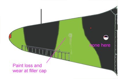
Many artists, and probably some modelers, as well, have gone somewhat astray when weathering their various Yak fighters in regards to these fuel gauge and filler cap items. The most usual miscalculation here is to apply staining and streaking aft of the instrument face (perhaps because it is so obvious). This would not be correct.
The filler cap is the item which is removed to refuel the aircraft, and around
which the majority of the weathering should be applied. The instrument itself
is not removed normally, and so therefore should demonstrate no more weathering
than any other panel line on the model.
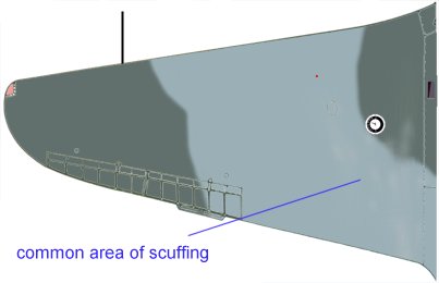
Scuffing and abrasion of the wing surface, however, is a different matter. Here
the area around the face might well be affected, and also the area around the
filler cap, as well. The amount of such weather, of course, is at the discretion
of each modeler, but it is best to keep in mind what type of weathering should
be represented at each position.
So, there it is--accurate fuel filler and gauge information for Yak fighters. We'll all be looking forward to seeing this material appearing on finished model kits soon.