Zveno 'Aviamatka'
By Ken Duffey
Zveno 'Aviamatka'By Ken Duffey |
|
Background
In June 1931, Vladimir Sergeyevich Vakhmistrov of the Soviet NII-VVS (Scientific Research Institute of the Air Forces) suggested a method of escorting bombers by means of fighters carried on the bomber's wings.
The first proposal involved a twin-engined TB-1 bomber with two I-4 (ANT-5) fighters attached to the upper surface of the bombers wings.
According to the specifications, the full range of the I-4 was 341 miles but was estimated to increase to 372 miles at release because it did not need to take of and climb to altitude. The radius of action of the TB-1 bomber with a normal bomb load was 217 248 miles. Hence the I-4 escorts could cover the TB-1 for its entire combat radius.
The Russian word Zveno has no direct western equivalent and is normally translated as flight but it can also mean link or coupling. In the first experiment Zveno-1, the I-4 fighters were attached by their axles to the TB-1 by means of a tubular pyramid framework - known as a spider - mounted on top of the bombers wings.
The tail of the I-4 rested on a triangular folding strut. The spiders locks were opened by a wire pulled from within the bombers cockpit, the tail release being made by the pilot of the fighter.
The first successful flight of this combination was made on 3 December 1931.
Further flights were made to prove the concept and it was suggested that the larger, four-engined TB-3 bomber be used as the mother ship. The experiments continued and produced a whole line of different Zvenos with varying combinations of parasites culminating in the operational use of the Zveno-SPB to bomb the oilfields of Constanta in Romania during the Great Patriotic War.
The various combinations are listed below :-
| Zveno-1 | TB-1 with two I-4 fighters attached on top of the wings. First flight 3 December 1931. | |
| Zveno-2 | TB-3/M-17 - (M-17 engines) with three Polikarpov I-5 fighters one on each wing plus one on top of the centre fuselage. First flight, summer 1933. | |
| Zveno-3 | Proposal to fit a TB-3/M-17 with two monoplane fighters under the wings. The proposed fighter was to be the Grigorovich IP-1, but its progress was delayed so it was decided to use the Grigorovich I-Z monoplane fighter on a trapeze under the fuselage instead. This trapeze could be set in two positions takeoff and in-flight but this led to the only Zveno tragedy when the trapeze was not lowered properly and when the I-Z was released, it was sucked up under the TB-3s fuselage. The pilot, Alexei Korotkov would not bail out for some reason, and he was killed when the combination landed and the I-Z was torn away. First flight, Summer 1934. | |
| Zveno-4 | This was a proposal to develop a special tug aircraft to get the heavily laden composites airborne | |
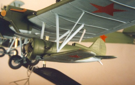
| Zveno-5 | This was a TB-3/M-17 with a Grigorovich I-Z monoplane fighter mounted on a trapeze under the bombers fuselage. The trapeze was hinged at its rear end and could be swung down to launch and recover the I-Z. The fighter itself was fitted with a mooring skid and grab hook on top of the fuselage in front of the cockpit. First flight 23 March 1935. | |
| Zveno-6 | Designed as a TB-3/M-17 with two Polikarpov I-16 monoplane fighters on a fixed triangular mounting under each wing. To improve communication between the fighter and bomber, they were fitted with an intercom. Fuel and oil hoses connected the fighter to the mother ship. First flight, December 1934. | |
| Zveno-7 | This involved a TB-3/M-17 with two Polikarpov I-16 fighters mounted under the wings on a trapeze. The trapeze fitted outboard of the outer engine nacelle orientated along the wingspan. It was pivoted about the inner end and swung down inwards to launch and retrieve the I-16s. The I-16s had a latch fitted on a triangular structure in front of the cockpit which engaged a bar on the trapeze but hooking up to the trapeze in flight proved to be complicated and was not always successful. Flown during 1938. | |
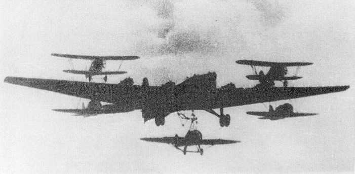
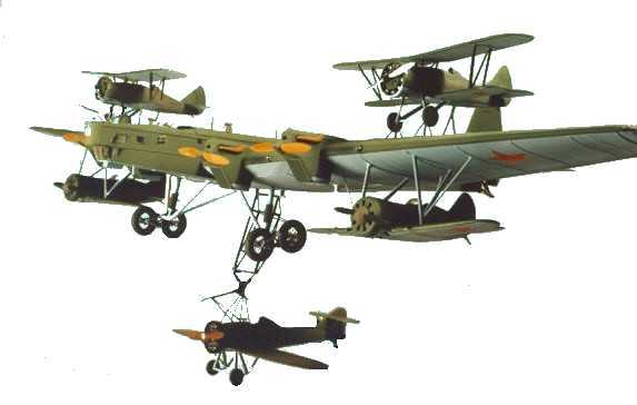
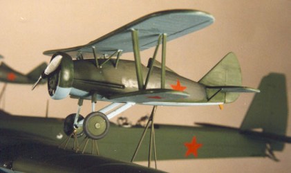
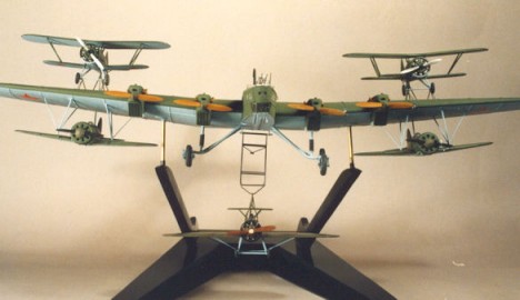
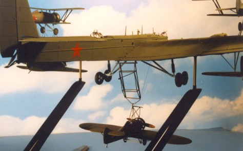
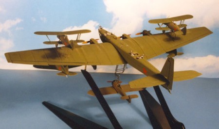
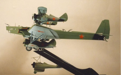
| Aviamatka-PVO | Literally an airborne alert proposal for an Air Defence Mother Ship designed to cruise around for five to six hours with four fighters attached ready to uncouple and defend remote areas or a naval task force. It was estimated that such a composite could replace 24 conventional fighters operating in groups of four and flying in shifts. To prove the concept Vakhmistrov decided to combine all three versions of the Zveno into one composite the Aviamatka-PVO. This combination had no less than FIVE fighters attached two I-5 biplanes mounted on spiders above the outer wings, two I-16 monoplanes on tubular struts under the wings and a single Grigorovich I-Z monoplane fighter on a trapeze under the centre fuselage. The TB-3 could take off with the I-5s and I-16s attached, but the I-Z had to take off separately and attach in flight. The first flight of this huge composite took place in November 1935. | |
| Zveno-SPB | This combination was proposed on 14 August 1934 for a long-range bomber carrying smaller fighter-bombers. The slower bomber would carry the smaller fighter-bombers to within range of the target and release them. The faster fighter-bombers would be better able to avoid the enemy defences and strike their targets unmolested. The combination eventually emerged as a TB-3/AM-34FRN (AM-34 engines) with two I-16SPB fighter-bombers under the wings. The I-16SPB (Skorostnykh Pickirujuschikh Bombardirovschikov High-Speed Dive Bomber) had reinforced wing spars and an additional oil tank fitted. It was able to carry a pair of FAB-250 (550lb) bombs on racks under the wings and was attached to the TB-3 on tubular triangular-shaped struts under the outer wings. The first flight took place in July 1937 and the combination was used successfully on July 26 1941 to attack the oilfields at Constantsa in German-occupied Romania. Following this success, on the night of 13 August 1941, the Chernavado bridge that carried an oil pipeline across the Danube was attacked and destroyed. |
In addition to the above listed Zveno combinations, Vakhmistrov also proposed other interesting concepts such as a transport glider with a towing fighter mounted underwing, a Pe-8 four-engined heavy bomber with two MiG-3 fighters underwing, another Pe-8 with two I-16SPBs, a flying bomb composite similar to the German Mistel, a flying torpedo and a GST (Catalina) flying boat with two I-5s on top of the wings.
The Model
|
I did consider converting the Matchbox Boeing P-12E kit into an I-5 and even went so far as to obtain a couple at an IPMS (UK) show. Later, on a trip to St Petersbourg, I managed to pick up a couple of excellent vacform kits of both the I-5 and I-Z. So, with all the necessary aircraft kits to hand, I was ready to start.
Tupolev TB-3
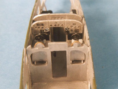
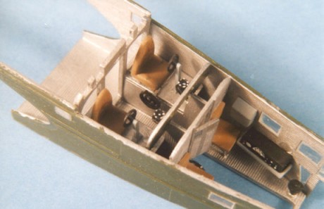
This is the standard ICM TB-3 kit with just some minor modifications. The kit itself is well moulded with excellent corrugated surface detail. The breakdown of parts makes it rather complicated to build, but providing that one proceeds carefully, a good model should result. The cockpit and interior is well detailed with lots of floors and bulkheads to be assembled and lined up. The instructions call for the interior to be painted green, but I decided to use flat aluminium.
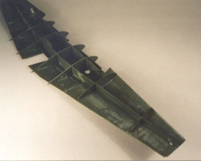
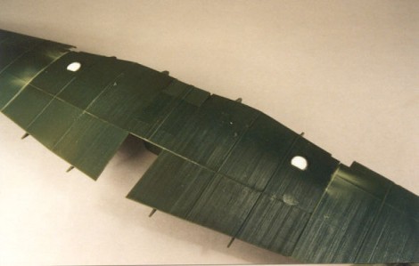
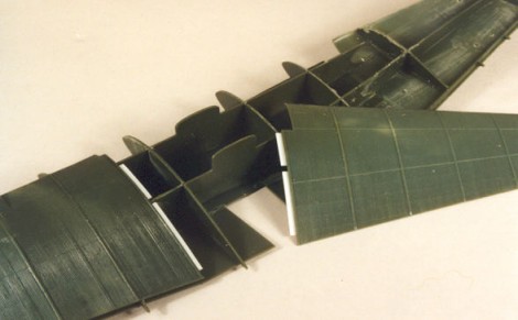
The wing is made from a series of spars and ribs and one should take care to
make sure everything is in alignment at all stages of construction. The wing
outer skins comprise no fewer than 24 parts 6 lower wing sections, 6 upper
sections, 4 leading edges, 2 wingtips, 2 flaps and 4 aileron parts. I did not
use the dustbin turrets and blanked off the holes in the lower wing with plastic
card. I also used lengths of plastic card to make overlapping ledges between
the upper wing skins. I had a bit of trouble getting the wing skins to fit over
the interior ribs and spars and had to rub the ribs down particularly at the
leading edge. But in the end it all fitted together.
 |
|
|
|
|
|
|
|
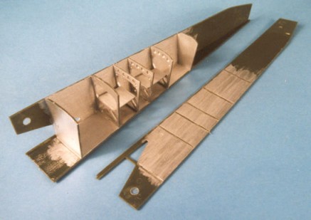
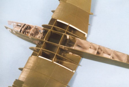
The fuselage is again broken down into lots of parts with flat side, top and
bottom panels fitted to interior bulkheads to make up the rectangular fuselage,
so lining it all up is an essential task. With the single-piece fin, rudder,
tailplane and elevators attached it is time to start on the engines.
|
|
|
|
Dials are added from Reheat decals |
|
|
|
|
|
The kit has four neatly detailed M-17 engines, mounted on bearers, located inside nacelles made up from side, top, bottom and front parts. The whole is finished off with well detailed exhaust pipes, propellers and spinners. I didnt, but it would be possible to open up the engine panels and add detail especially with the Eduard etched-brass detail set providing the drop-down leading-edge servicing platforms.
I had a little trouble getting the spinners to fit over the propellers and had to gouge out their interiors to make them fit.
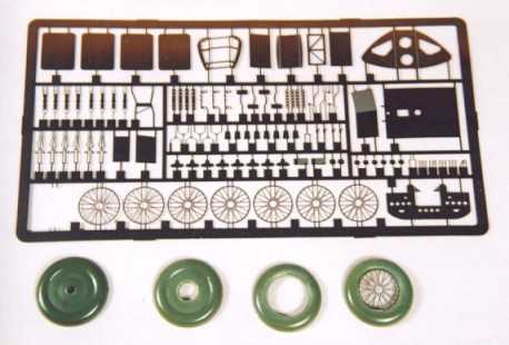
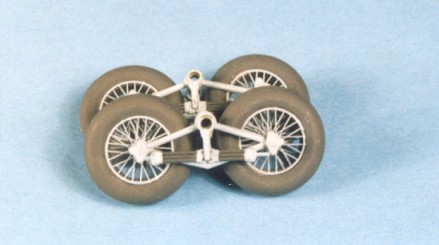
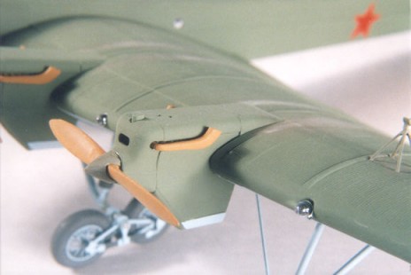
ICM supply a beautifully detailed tubular bogie for the tandem-wheeled undercarriage, but the two-part wheels have solid centres. This is OK as far as it goes, but most photographs of TB-3s show them without the wheel hub covers to expose the spoked wheels. Besides, I think that spoked wheels add to the gangly appearance of these huge bombers, so I purchased the Eduard etched-brass detail set (number 72 335). This contains a new instrument panel, with film for the instruments, lots of interior detailing such as control wheels, seat belts, parts for the machine guns, wheel spokes, engine access panels and drop-down service platforms for the wing leading edges and numerous other bits and pieces. As I was so far down the road with my construction, I only used the wheel spokes, saving the rest for my next TB-3 (!)
I removed the wheel centres in stages first drilling out a centre hole and then gradually increasing the drill size up to the largest drill I had. I had to resort to a scalpel blade to gouge out the final bits out to the wheel rim. I left a small part of the rim for the replacement spokes to fit on. Each of the two wheel halves were then cemented together, but there was now a hole inside the rim, so this was filled with a length of plastic card wrapped around the inside diameter of the tyre. The tyre and inside rim was painted very dark grey and the etched-brass spokes underside blue. When the paint had dried, I carefully attached one spoked hub to the tyre rim with superglue, then turned it over and, using a short length of plastic rod to line up the axle holes, attached the spokes on the other side. The effect is quite good and represents the complex tandem spoked wheels much better than the solid hubs in the kit. It isnt strictly accurate in that the spokes are flat rather than being conical, but it will do for me!
|
|
|
|
|
|
|
|
|
|
|
|
|
Note that ICM have released another version of the TB-3 - this time called
a TB-3/SPB but it isn't strictly accurate for the SPB variant. The TB-3 used
with the I-16SPB was a much later model with AM-34FRN engines driving four-bladed
propellers. It also had single large wheels and a redesigned rear fuselage with
a gun turret. I don't have this kit - but it looks like it could be used
as a basis for a Zveno-6, but it would require major modification to make an
SPB.
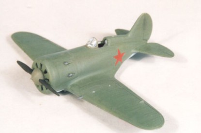
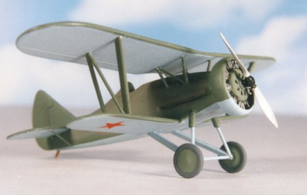
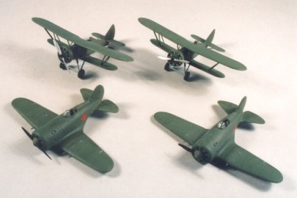
Polikarpov I-16
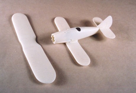
For the underwing I-16s I used the Amodel kit as it represents an early Type
5/6. It isnt the best of kits, but once cleaned up and assembled, it does the
job. I fitted the undercarriage in the closed position and filled in the gaps.
|
|
|
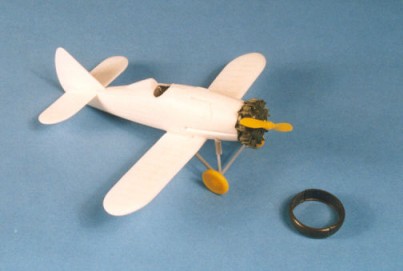
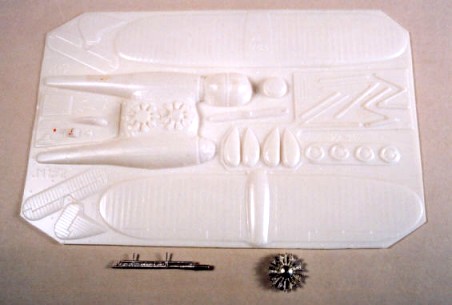
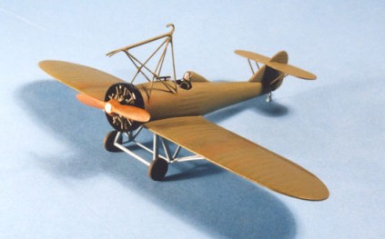
ANT I-5
This is a vacform kit from a Russian company called KASK. Not much to say about
it the usual vacform style with two fuselage haves, two-part upper and lower
wings, tailplanes and fin. I added some interior detail and replaced the kits
vacform engine, propeller, wheels and Townend ring with parts from the Matchbox
Boeing P-12E kit. The undercarriage legs and wing struts were replaced by Contrail
strut with a plastic rod axle.
|
|
|
|
|
|
|
|
|
|
|
|
|
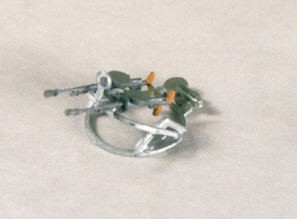
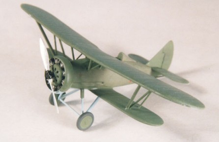
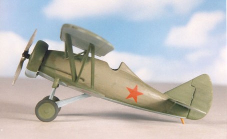
Grigorovich I-Z
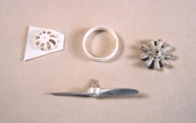
The Grigorovich I-Z is even more rare than the I-5, but once again, KASK came to the rescue with a neat little vacform kit. This went together well without any problems. I had to make up the complex undercarriage strutting from Contrail struts and I replaced the vacform propeller and kit-supplied metal engine with more detailed Aeroclub white metal items.
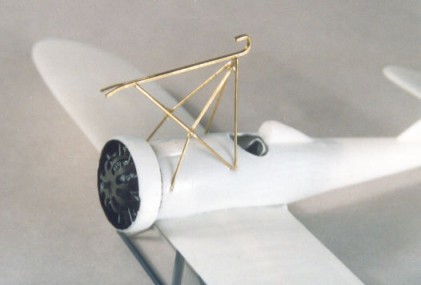
The complicated trapeze attachment structure with the hook in front of the
cockpit was made up from lengths of brass wire superglued into place.
|
|
|
|
Replacement Aeroclub engines and propeller with vacform Townend ring and engine cover. |
|
|
|
|
Close-up of the trapeze hook and mounting structure made from brass rod. |
|
|
|
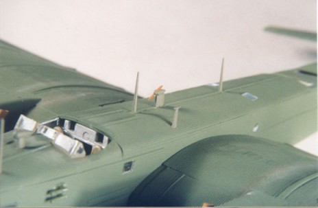
Painting and Finishing.
With all the aircraft constructed, they were airbrushed with Aeromaster Warbird
Colors Lt. Blue undersides and Topside Green. The ICM decals proved to be
a disaster and broke up when immersed in water, so I had to find some suitable
red stars in the spares box. I couldnt find any large enough for the wing upper
surface, but as I cant tell whether this particular Zveno had them, I am not
too worried. The I-5, I-16 and I-Z only appear to have underwing and fuselage
roundels arent Soviet marking boring ?
|
|
|
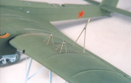
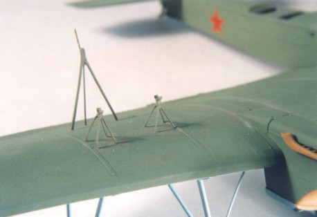
Now it was time to attach everything ! I made spiders for the I-5s
from brass rod and fixed them into the TB-3 wing top surface, together with
the rear triangular struts.
|
|
|
|
|
The underwing I-16s were attached to triangular mountings made up from Contrail
aerofoil section struts, cut to length and pinned into place under the wing
with brass rod. Brass rod pins also connected the struts to the upper surface
of the I-16 wings.
|
|
|
|
|
The biggest problem was getting everything to line up correctly both from the front and sides. Lots of adjustment was necessary until I was satisfied that the parasites were in the correct position when viewed from the head on and adopted the correct attitude when viewed from the side.
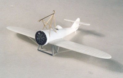
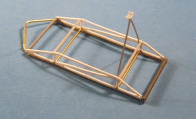
To display the I-Z I decided to make a working trapeze so that it could be shown lowered in flight with the I-Z attached and retracted on the ground minus the I-Z.
The trapeze took some working out as to its shape and geometry, but after studying
all my available photos and drawings, I came up with a sketch of its shape.
I made it up from plastic card and brass rod with a plastic tube forming the
rear cross-member.
|
|
providing the pivot. The triangular strut at the rear rests on the rear fuselage of the I-Z when the trapzeze is in the retracted position. |
With two mounting lugs attached to the bottom of the TB-3, I was able to mount the trapeze with a brass rod axle passed through the lugs and the tube on the trapeze that allowed it to pivot down hinged about its rear end. To hold it in place on the real thing, a wire runs from the front end and looks as though it goes into the fuselage. I assume there is some sort of winding mechanism to raise and lower it. I reproduced this on my model by having a short length of thread from the trapeze passing through an eyelet with a short length of plastic rod to act as a stopper when the trapeze is extended. By pulling on the thread and hooking the plastic rod through a small piece of plastic card with a slot in it, I am able to raise and lower my trapeze just like the real thing. Its a bit crude but it works and it isnt too obvious !
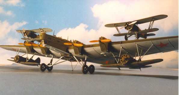
To display the whole combination in flight, I made a stand from an old plastic coat hanger and some plastic card. The coat hanger was cut in two to make two arms and they were mounted on a Vee-shaped base made from thick plastic card the whole lot being sprayed gloss black. I let some brass tube into the underside of the TB-3s wings and the whole thing sits on thick brass rod supports fitted into the wings and tops of the coat hanger arms. In this way I can show off the trapeze and I-Z fighter or I can remove the I-Z, retract the trapeze and show the model on its wheels with just the four fighters attached.
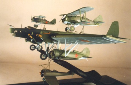
With the model on its stand and all five fighters attached, it makes you want
to say break to see all of them detach and fly off !!
|
|
|
 |
 |
| 'Break' | Rear three-quarter view |
 |
|
| Looking down on the whole thing. | |
 |
 |
| Side view of the combination. | Another shot of the formation. |
 |
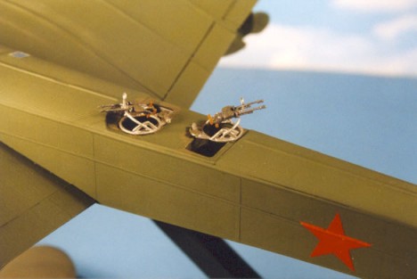 |
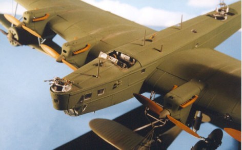
| View of the nose of the TB-3 | Close up of the rear machine gun mounts. |
 |
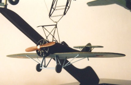 |
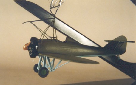
| Grogorivich I-Z on the lowered trapeze. | Another shot of the I-Z. |
The best reference I have found for the work of Vahkmistrov is in an issue
of the UK quarterly magazine - 'Air Enthusiast' for November/December 1999 -
Issue No 84. This contains an 18 page article by Col Vladimir Lesnitchenko on
the whole Zveno projects with lots of photos, drawings and maps.
Ken Duffey
February 2002