A Pretty Polly
...or, a Russian in Chinese Clothing....
By Bob Partridge
A Pretty Polly
|
|
The Hobbycraft Polikapov I-16 has been around for quite a while now and has been issued as several of the different types of this fighter--the Type 5, 6, 10, 17, 18, and 24 with differing armament levels. If you purchase the Academy kit, which are in fact the Hobbycraft mouldings re-issued under the Academy label, you get all of the variations in one box. The draw-back is that the basic kit only represents the later types, from type 10 onwards. If you want to be totally accurate it is only representative of the Type 24 onwards, albeit with some inaccuracies.
Although the basic size and shape altered only in small details through the different types there were numerous changes to specific areas, and development of the airframe, armament and engine, continued.
The Type 5/6 had no cowl guns and a fully enclosed cockpit with a forward sliding hood. The wing had fairly widely spaced ribs and the plywood leading edge wrapped around the upper edge for about ¼ of the wing chord, slightly less on the lower surface. The ailerons were long span, extending from the wing tip to the wing root. The exhaust arrangement was a single pipe through 7 of the 8 tear drop shaped ports around the cowling, with a twin pipe out of the top left, eighth port. As the series progressed (Type 10) the wing ribs were increased on the upper surface by the addition of half ribs, doubling the ribs to those shown in the kit. The leading edge plywood was increased to about ½ the chord on the upper surface, the lower surface remained the same through out the range. The ailerons were shortened at the inboard end by about 2 ribs ending at the wing break. Flaps were added to the wing/fuselage underside centre section. The exhaust port number was reduced to 6 and became more oval in shape with double pipes in the 2 lower ports as well as the upper left port. Cowling guns were added with their prominent gun fairings between cowling and fuselage. On Type 18 the spinner became an hemispherical shape, whereas before it had been a curve-sided cone. On the Type 24 the fuselage acquired an inspection/radio hatch on the starboard side as per the kit. The full sliding canopy of the Type 5 was reduced to a fixed windscreen and open cockpit on the Type 6 onwards. A reflector sight on late production Type 6 replaced the telescopic gun sight.
So, you can see that if you wish to model anything apart from a Type 24 there is quite a lot of work to be done... but we chose this hobby (collecting beer mats is beginning to look attractive).
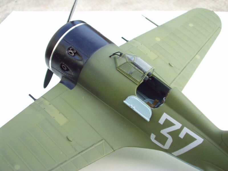
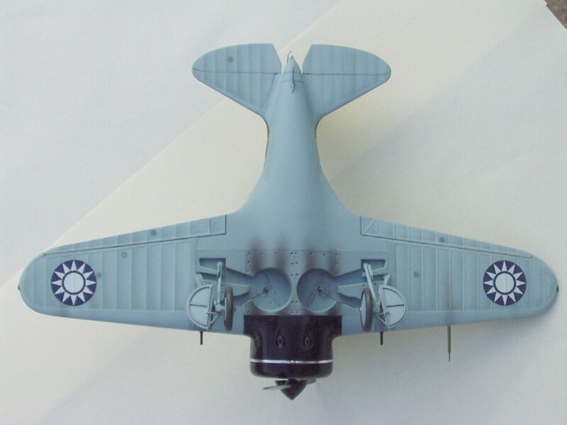
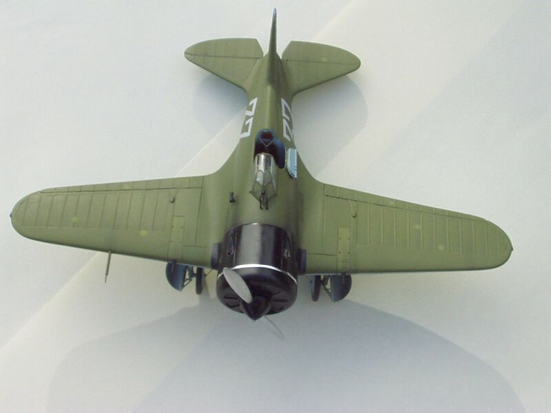
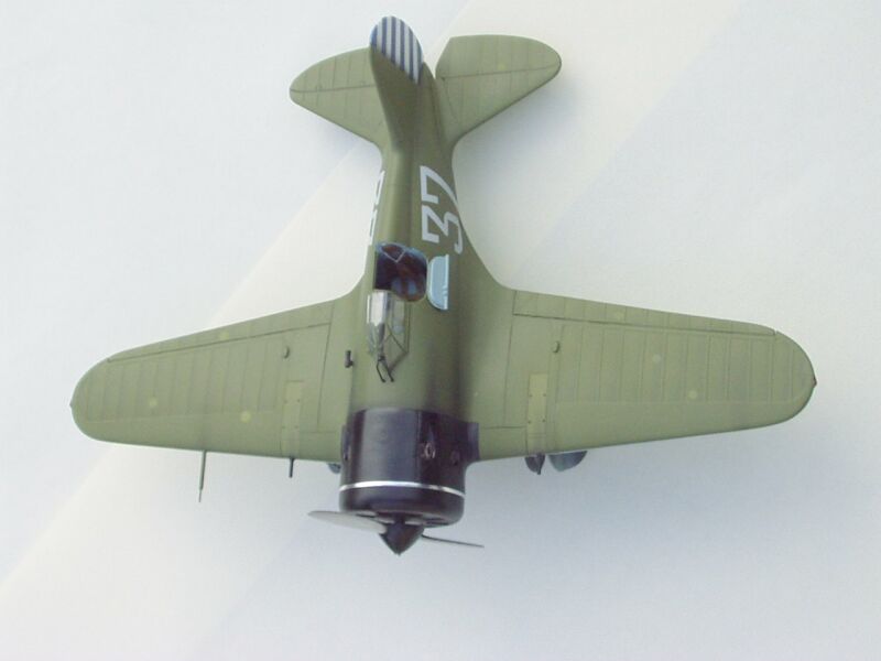
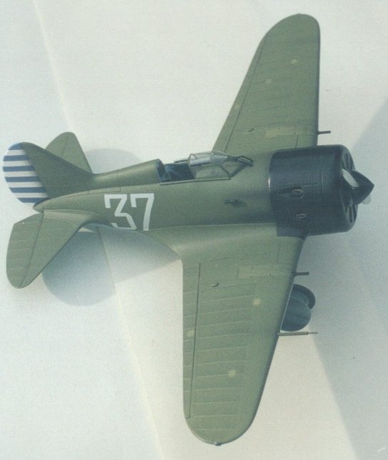
I wanted to model a Type 5 (White 37) as flown by A. V. Vorozhejkin of the VVS while an instructor with the Chinese in Manchuria during 1938, although officially a non-combatant Vorozhejkin reportedly shot down a 4-victory Japanese Naval pilot (K. Iwagochi). Oh well, I suppose thats what happens when they fly in front of you when youre testing the guns.
Armed with a folder full of information from Peter Vill, I set about the necessary work to convert and improve the Hobbycraft kit to a I-16 Type 5.
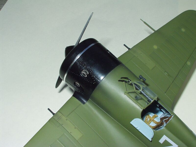
The first thing I did was to fill all the engraved lines on the fuselage, the hatch and cockpit door on the starboard side, the gun access hatches in front of the cockpit and the cowling lines (for this I used Super Glue). The lines that had been filled were then sanded flat and finally polished. The port side cockpit door was cut out as I wished to show off as much of the added cockpit detail as possible, but more of this later. The exhaust pipes in the outlet ports were removed with a new scalpel blade and the two lower ports were filled with shaped plastic card; these were coated with super glue. When dry these exhaust port fillers were sanded and polished smooth. New, correctly positioned exhaust ports were marked out on the under nose extension of the wing, then drilled out and filed to the required tear drop shape. The outlet ports on the fuselage sides were re-shaped at the same time.
The internal bulkhead, which also doubles as the engine fire wall, is located in a groove which aligns with the front openings of the exhaust ports. This is not a problem if building straight from the box, but it tends to spoil the effect of the corrected openings, I therefore cut scallops out of the circumference of the bulkhead in-line with the openings. The engine is not bad, but as it is virtually invisible I consigned it to the spares box, the front cowling vents being closed with shutters made from plastic card.
Exhaust pipes made from aluminum tubing were cut and the ends filed to the correct angle, these being attached in place in the ports using super glue.
The entire cockpit was scratch built using plastic card, rod, printers' litho
plate and various bits of copper wire. At the same time the wing spar, which was again scratch-built,
was added to support the cockpit flooring. The instrument panels varied slightly
from type to type but as it is set well forward and almost invisible I
used the kit item with the addition of a few bits of rod and sprue to represent
knobs and fuel selectors. The instrument panel was painted matte black and dry
brushed before individual items being picked out and gloss varnish added to
represent the dial lenses. The entire cockpit interior was primed with Halford
Grey before being spray painted with Aero Master 1194 Russian Under-surface
blue (information from the Modeling The VVS web site confirms that a large
number of I-16`s were in fact finished in this manner). Details were then picked
out in black before the area was dry brushed and given a wash of thinned down
black. I had based my scratch built seat on the item
copper wire. At the same time the wing spar, which was again scratch-built,
was added to support the cockpit flooring. The instrument panels varied slightly
from type to type but as it is set well forward and almost invisible I
used the kit item with the addition of a few bits of rod and sprue to represent
knobs and fuel selectors. The instrument panel was painted matte black and dry
brushed before individual items being picked out and gloss varnish added to
represent the dial lenses. The entire cockpit interior was primed with Halford
Grey before being spray painted with Aero Master 1194 Russian Under-surface
blue (information from the Modeling The VVS web site confirms that a large
number of I-16`s were in fact finished in this manner). Details were then picked
out in black before the area was dry brushed and given a wash of thinned down
black. I had based my scratch built seat on the item  found
in the Eduard etched set but further research led me to believe that this was
incorrect. I decided to replace it with another scratch built item, the base
of which was plunge moulded using a wooden master, the cushion being a piece
of corrugated plastic card. The seat belts were made from masking tape and appeared
to be of the British Sutton harness type, the seat being painted the same
colour as the interior, the cushion leather brown and the belts a light webbing
colour.
found
in the Eduard etched set but further research led me to believe that this was
incorrect. I decided to replace it with another scratch built item, the base
of which was plunge moulded using a wooden master, the cushion being a piece
of corrugated plastic card. The seat belts were made from masking tape and appeared
to be of the British Sutton harness type, the seat being painted the same
colour as the interior, the cushion leather brown and the belts a light webbing
colour.
The fuselage was now put together, trapping the cockpit and 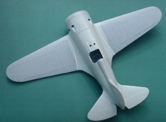 engine
bulkhead into place. I must say at this point that the fit of the 2 fuselage
pieces is best described as poor, and in the end I resorted to gluing it together
one section at a time. When dry, the instrument panel was fixed into place via
the wing opening and 2 holes drilled in the fuselage top surface between the
cockpit coaming and the instrument panel (these were used on the real aircraft
to illuminate the instruments).
engine
bulkhead into place. I must say at this point that the fit of the 2 fuselage
pieces is best described as poor, and in the end I resorted to gluing it together
one section at a time. When dry, the instrument panel was fixed into place via
the wing opening and 2 holes drilled in the fuselage top surface between the
cockpit coaming and the instrument panel (these were used on the real aircraft
to illuminate the instruments).
Work now started on the wings. The upper surfaces were glued to the lower section,
and when dry all detail outboard of the wing break was removed by sanding. Pieces
of Tamiya masking tape, pre-cut to shape, were attached representing the plywood
leading edge. 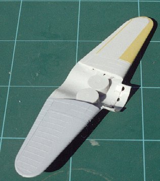 The
wing ribs were also represented in the same manner, but this time using thin
strips of masking tape. The whole assembly was then given several coats of primer.
This is done for three reasons: it seals the tape; fills any gap present at
the leading edge; and finally reduces that sharp stepped edge of the tape. The
wing requires other minor details to be added, such as the wheel well window
and well stiffeners (which my information shows are fitted at an angle, front
end inwards toward the fuselage).
The
wing ribs were also represented in the same manner, but this time using thin
strips of masking tape. The whole assembly was then given several coats of primer.
This is done for three reasons: it seals the tape; fills any gap present at
the leading edge; and finally reduces that sharp stepped edge of the tape. The
wing requires other minor details to be added, such as the wheel well window
and well stiffeners (which my information shows are fitted at an angle, front
end inwards toward the fuselage).
When happy with the wing assembly it was attached to the fuselage. At this
stage you will wish you had shares in a model filler company. When you have
filled the wing to fuselage joints and all is blended in and smooth, the engine
cowling can be test fitted. Luckily, I did this because I had left the cowling
shutters slightly open and I now realized that I could see day light through
the 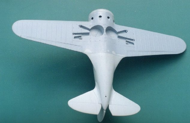 exhaust
ports; this was because I had not used the engine. This fault was simply overcome
by cutting a circle of plastic card and fitting it into the nose of the fuselage,
having pre-painted it black. This done the cowling was then permanently fixed
into place, ensuring correct alignment.
exhaust
ports; this was because I had not used the engine. This fault was simply overcome
by cutting a circle of plastic card and fitting it into the nose of the fuselage,
having pre-painted it black. This done the cowling was then permanently fixed
into place, ensuring correct alignment.
Minor items such as gun barrels, pitot tube and the cockpit door were made
using brass tube and printers' litho plate. Apart from the door, these items
were added prior to painting.
My attention was now directed to the undercarriage and how this could be improved.
The  main
oleo leg and rear brace, which is a single piece moulding, was the kit item.
These were fixed into place with liquid cement and when happy with the alignment
the fixing was reinforced with super glue. The third strut, which was also the
kit item, was offered into place and was found to be such a poor fit that I
replaced it with brass rod bent to fit the locating points. The main gear door
was the kit item but sanded down to less than half its original thickness, the
interior frame work being made from 10 X 20 thou strip cut to size, flattened
wire being used to represent the hinges and rods. The other doors were made
from 10 thou plastic sheet and detail added with strips of Tamiya masking tape,
these being fixed into place on the gear struts with super glue. At this point
my grave digger shovel sized hands worked against me and I must confess to breaking
off one of the wheel axles, I replaced both by drilling through the leg and
inserting brass tube which was pre-cut to length. The tail skid supplied in
the kit was replaced with an item again made from brass rod filed to shape (OK,
OK, I admit it, I likes Brass).
main
oleo leg and rear brace, which is a single piece moulding, was the kit item.
These were fixed into place with liquid cement and when happy with the alignment
the fixing was reinforced with super glue. The third strut, which was also the
kit item, was offered into place and was found to be such a poor fit that I
replaced it with brass rod bent to fit the locating points. The main gear door
was the kit item but sanded down to less than half its original thickness, the
interior frame work being made from 10 X 20 thou strip cut to size, flattened
wire being used to represent the hinges and rods. The other doors were made
from 10 thou plastic sheet and detail added with strips of Tamiya masking tape,
these being fixed into place on the gear struts with super glue. At this point
my grave digger shovel sized hands worked against me and I must confess to breaking
off one of the wheel axles, I replaced both by drilling through the leg and
inserting brass tube which was pre-cut to length. The tail skid supplied in
the kit was replaced with an item again made from brass rod filed to shape (OK,
OK, I admit it, I likes Brass).
Now to paint. The fuselage was masked off to spray the cowling which was done using Halford Gloss black. Once dry the masking was removed and the cowling was then masked off. Using this masked area as a hand hold, the rest of the model was primed with Halford grey primer. At this point I check the model for any defects that the primer exposes, correct and re-prime as required. Smaller items that had been mounted on cocktail sticks were primed at this time (Wheels, Propeller and spinner, etc.).
The under surface was painted first using 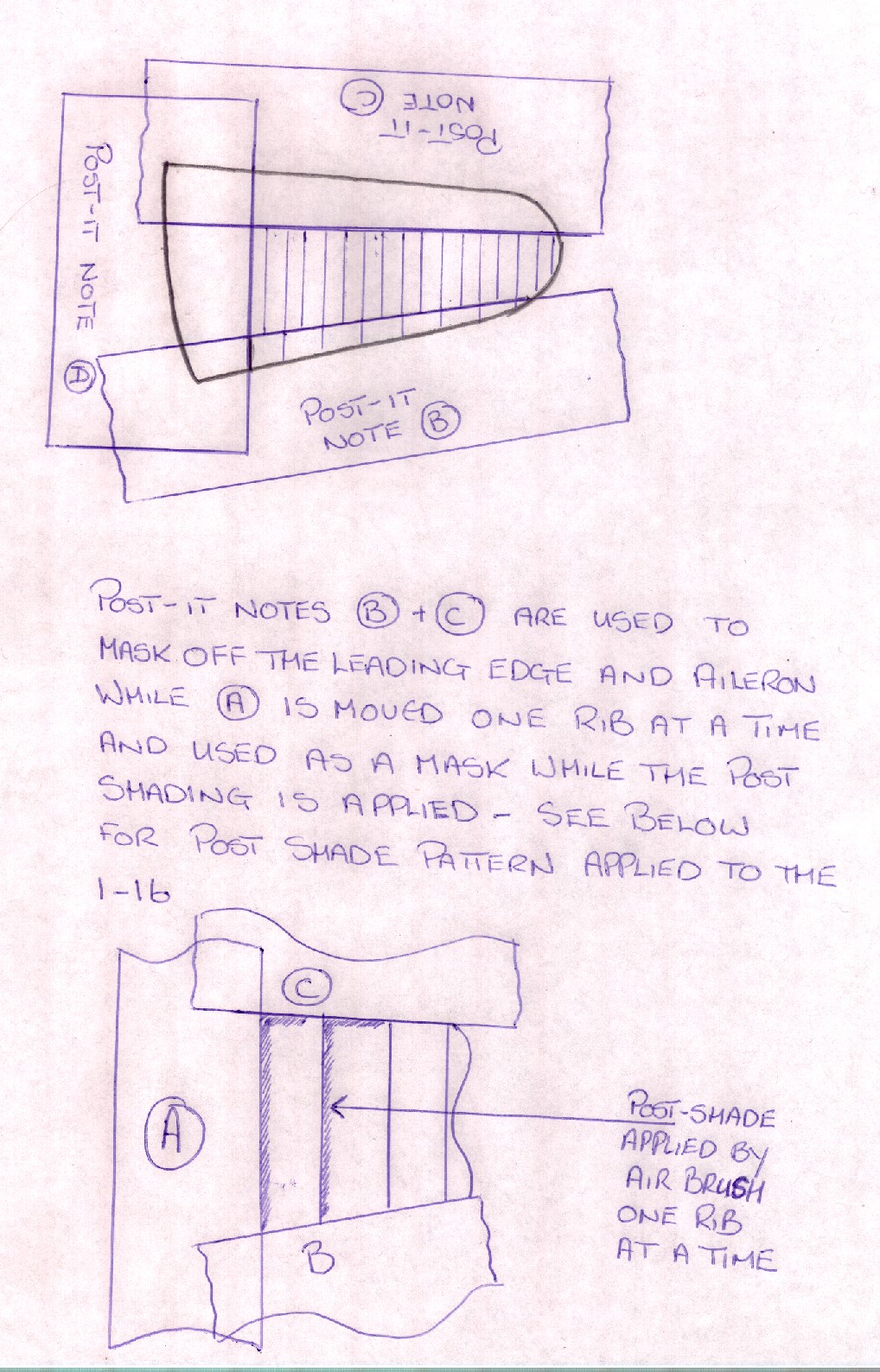 Aero
Master Russian Light Blue 1194 (Acrylic). This forms the base coat which I then
work on to weather and give depth in a manner similar to that described by Peter
Vill. Basically, I lighten the base mix and apply this to areas such as fabric
covered elevators and ailerons. In the case of this model this meant the whole
of the outer wing and tail plane. Once this had been done I mixed a darker shade
of the base colour and with this I sprayed some individual panels. I also use
this colour to highlight the wing ribs. This is done by masking off the leading
edge with a post-it note; the individual wing ribs are also masked off with
a post-it note. Starting at the in-board rib, I spray an L shaped pattern
of the darker colour along the leading edge and down the rib, each rib being
done in turn. Don`t worry if it looks over done, as you can blend it in
using a very thinned wash of the original base colour sprayed lightly overall.
Having allowed sufficient time for the under-surface to dry I masked off the
upper/lower colour demarcation line. The rudder was painted white and then masked
to allow the application of 6 blue stripes, 12 in total, this was then masked
off prior to painting the top surface. The upper-surface was sprayed using acrylic
paint supplied by Erik Pilawskii via Peter Vill. The colour used was
AII Green (Old), it appears that in service this paint oxidizes and darkens
with age. The technique used and described for weathering the lower surface
was repeated on the top surface. Exhaust and gun blast stains were added to
both lower and upper surfaces using a light spray of thinned black; take your
time with this action and build it up slowly. The final act of weathering/aging
was to apply lighter circular patches of green and blue to the respective surface
to represent bullet hole repairs.
Aero
Master Russian Light Blue 1194 (Acrylic). This forms the base coat which I then
work on to weather and give depth in a manner similar to that described by Peter
Vill. Basically, I lighten the base mix and apply this to areas such as fabric
covered elevators and ailerons. In the case of this model this meant the whole
of the outer wing and tail plane. Once this had been done I mixed a darker shade
of the base colour and with this I sprayed some individual panels. I also use
this colour to highlight the wing ribs. This is done by masking off the leading
edge with a post-it note; the individual wing ribs are also masked off with
a post-it note. Starting at the in-board rib, I spray an L shaped pattern
of the darker colour along the leading edge and down the rib, each rib being
done in turn. Don`t worry if it looks over done, as you can blend it in
using a very thinned wash of the original base colour sprayed lightly overall.
Having allowed sufficient time for the under-surface to dry I masked off the
upper/lower colour demarcation line. The rudder was painted white and then masked
to allow the application of 6 blue stripes, 12 in total, this was then masked
off prior to painting the top surface. The upper-surface was sprayed using acrylic
paint supplied by Erik Pilawskii via Peter Vill. The colour used was
AII Green (Old), it appears that in service this paint oxidizes and darkens
with age. The technique used and described for weathering the lower surface
was repeated on the top surface. Exhaust and gun blast stains were added to
both lower and upper surfaces using a light spray of thinned black; take your
time with this action and build it up slowly. The final act of weathering/aging
was to apply lighter circular patches of green and blue to the respective surface
to represent bullet hole repairs.
The whole model was now  given
a coat of Halford Gloss Lacquer, when this had dried the decals that E. Pilawskii
had supplied ( White 37) were applied, the Chinese Nationalist Stars came from
the Hobbycraft P-40 kit. It must be said that both sets of decals were excellent
and pulled down skin tight with only a small amount of decal solution. The next
action is a bone of contention between P. Vill and myself. I apply a second
coat of gloss lacquer over the decals (he does not, and believes this to be
a waste of money--but he would!) to hide the decal film. Every time that I neglect
to carry out this second coat, you have been able to see the decal film. I don`t
know what he does, but Mr.Vill does not suffer with the same problem.
given
a coat of Halford Gloss Lacquer, when this had dried the decals that E. Pilawskii
had supplied ( White 37) were applied, the Chinese Nationalist Stars came from
the Hobbycraft P-40 kit. It must be said that both sets of decals were excellent
and pulled down skin tight with only a small amount of decal solution. The next
action is a bone of contention between P. Vill and myself. I apply a second
coat of gloss lacquer over the decals (he does not, and believes this to be
a waste of money--but he would!) to hide the decal film. Every time that I neglect
to carry out this second coat, you have been able to see the decal film. I don`t
know what he does, but Mr.Vill does not suffer with the same problem.
At this stage I add thinned black paint to any panel line, etc., that I wish to stand out a little more. If it overflows dont worry as it is on the gloss coat; just let it dry and then wipe/polish it off.
 When
happy with the above operations and their effect, the model was given a coat
of matte varnish, again of the water based type. When this is dry the model
was checked over for any areas or effects that require touching up. When totally
happy with the end result a final coat of matte varnish was applied. Small items
such as the landing gear retraction cables were now added as was the vac-form
canopy (which was supplied by Peter Vill and I think is from the Falcon set),
the last items being the scratch built gun site and fuselage mounted venturi.
When
happy with the above operations and their effect, the model was given a coat
of matte varnish, again of the water based type. When this is dry the model
was checked over for any areas or effects that require touching up. When totally
happy with the end result a final coat of matte varnish was applied. Small items
such as the landing gear retraction cables were now added as was the vac-form
canopy (which was supplied by Peter Vill and I think is from the Falcon set),
the last items being the scratch built gun site and fuselage mounted venturi.
There you have it: one I-16 Type 5 as flown by the Chinese ??? against the Japanese invaders of Manchuria. It is my intention to model more VVS aircraft that were used against the Japanese in Manchuria but for that you will just have to wait a little while.

I would like to thank Erik Pilawskii for his help in supplying information on the aircraft that I have modeled, and also Peter Vill who moans a lot when I use his computer to go on line but at the end of the day is a very good friend.