I-16 Type
29
1/48 Academy kit with Airwaves resin conversion set
By Ira Campbell
I-16 Type
29
|
|
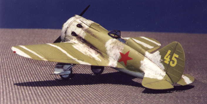
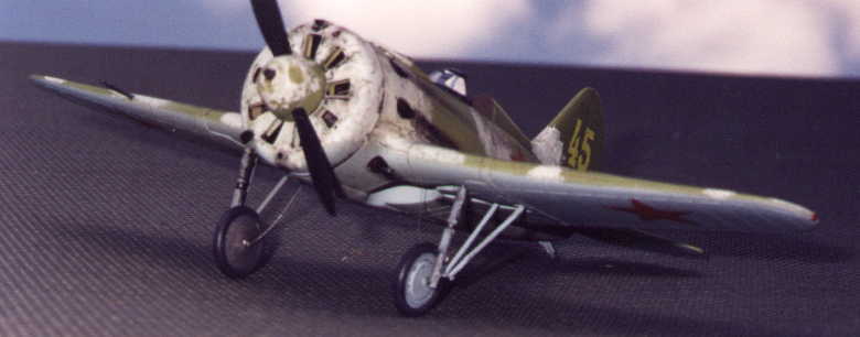
I will not delve deeply into the history and development of the Polikarpov I-16 fighter, as it has been printed many times in various sources. I find it an interesting type, as it combined some WWI construction techniques, like the Pfalz angled plywood fuselage skin, with cutting edge technology for its day, namely being a low-wing monoplane. The type 29 was the last development of the I-16, replacing wing-mounted guns with a central cannon, which fired through the propeller arc, underneath the radial engine.
My primary goal in building this model was to test the fit of the then upcoming Airwaves resin conversion set. My test shot arrived from the UK without instructions which had yet to be printed. However, the sculptor of the set, Mr. Peter Vill, was kind enough to email me instructions. My thanks go to him for said instructions, as well as for some additional material on the I-16 interior and structure.
 I
had built the I-16 kit before, as released by Hobbycraft, but there were a few
surprises in the Academy box. The decals are of better quality, some parts have
been tweaked with better detail, there are two cowl pieces provided, there are
underwing stores, and the builder has the choice of wheels or skis for the undercarriage.
Out of the box, the Academy kit will build into a reasonable, if generic, I-16
and satisfy the vast majority of modelers wanting one for their collection.
I
had built the I-16 kit before, as released by Hobbycraft, but there were a few
surprises in the Academy box. The decals are of better quality, some parts have
been tweaked with better detail, there are two cowl pieces provided, there are
underwing stores, and the builder has the choice of wheels or skis for the undercarriage.
Out of the box, the Academy kit will build into a reasonable, if generic, I-16
and satisfy the vast majority of modelers wanting one for their collection.
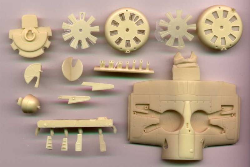
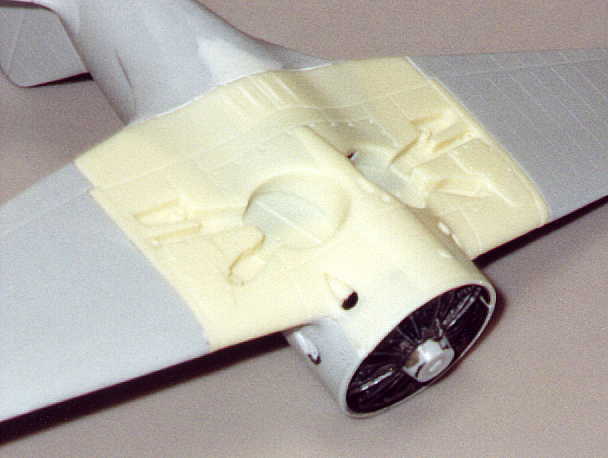
The Airwaves resin set provides the parts necessary to build a type 29 plus more detailed landing gear doors and separate exhaust stubs. They go so far as to include two cowl pieces, for early or late production type 29s, and the appropriate cooling baffles which mount inside the cowl. If I were to be very picky, I would point out that the cowl pieces and landing gear doors are a little thick in scale. However, if the parts were any thinner, they would not cast properly, so this is a necessary compromise from the production standpoint. The modeler can easily sand the cowl from the inside and sand the outside surfaces of the gear doors to closer approximate scale appearances. This would benefit the cooling baffles in particular.
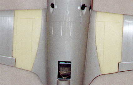
I started the conversion by doing the only significant surgery required of
the modeler, cutting out the wing center section. If one holds the resin center
section/wing bottom part up to the kit part, the cut is readily apparent. I
marked the kit part with a permanent marker inside the cut line. Note that the
cut is "stepped" to include the kit ailerons. I scribed the kit part
with a hobby knife a few times, just inside the marked cut  lines,
about even with the inside edge of the ailerons. Then I gently bent the part
at the scribed line and it snapped off where scribed. I found I had to remove
remnants of the wheel wells from inside the outer wing so the resin part would
fit. If you are using underwing stores, open the appropriate holes now. At this
point, I cleaned up the kit upper wing parts, lined them up carefully with the
lower wing parts, and cemented them together. After the cement was thoroughly
dry, I began dry fitting the outer wings to the resin center section, filing
away excess plastic until the fit was just right. With patience and care, one
can join the parts without filler. CA adhesive was used to join the plastic
with the resin, though one could also use epoxy. I mated the wing sections at
this time, but some may wish to wait until the center section part is in place
on the fuselage. Also, the modeler may wish to remove the kit exhaust stubs
at this stage. I used a motor tool with a very small grinding bit. Remember,
the tool will melt plastic easily, so proceed slowly. It doesn't take much to
remove these little bits.
lines,
about even with the inside edge of the ailerons. Then I gently bent the part
at the scribed line and it snapped off where scribed. I found I had to remove
remnants of the wheel wells from inside the outer wing so the resin part would
fit. If you are using underwing stores, open the appropriate holes now. At this
point, I cleaned up the kit upper wing parts, lined them up carefully with the
lower wing parts, and cemented them together. After the cement was thoroughly
dry, I began dry fitting the outer wings to the resin center section, filing
away excess plastic until the fit was just right. With patience and care, one
can join the parts without filler. CA adhesive was used to join the plastic
with the resin, though one could also use epoxy. I mated the wing sections at
this time, but some may wish to wait until the center section part is in place
on the fuselage. Also, the modeler may wish to remove the kit exhaust stubs
at this stage. I used a motor tool with a very small grinding bit. Remember,
the tool will melt plastic easily, so proceed slowly. It doesn't take much to
remove these little bits.
 At
this point I moved to the cockpit. The kit supplies a very basic "office."
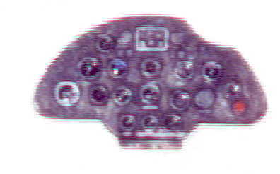
There is a floor/rear bulkhead, seat, stick, and instrument panel. The instrument
panel is actually pretty decent, so I painted mine black and picked out a few
details in red, blue, gray, and grimy black, finishing up with Future floor
polish applied to the instrument faces to represent glass. The seat is not quite
accurate, but it had nothing to do with the fit of the conversion set, so I
added harnesses cut from wine bottle foil to disrupt the lines a little.
At
this point I moved to the cockpit. The kit supplies a very basic "office."
There is a floor/rear bulkhead, seat, stick, and instrument panel. The instrument
panel is actually pretty decent, so I painted mine black and picked out a few
details in red, blue, gray, and grimy black, finishing up with Future floor
polish applied to the instrument faces to represent glass. The seat is not quite
accurate, but it had nothing to do with the fit of the conversion set, so I
added harnesses cut from wine bottle foil to disrupt the lines a little.
The resin center section has a rectangular window in the starboard wheel well. What does this have to do with the cockpit? Well, to see through this window, the pilot looked down past his right leg. That's right, there was no floor here. In fact, the channels for the pilot's feet between the seat and the rudder pedals were the only floor. I reduced the width of the kit floor piece to about the width of the seat, leaving the full width only at the front and rear, so the floor would mount to the kit attachment points. The front attachment point is about where the wing spar would be, and is a fair representation. A purist would want to add more detail underneath. I used .100" styrene channel stock for the foot channels.
The kit stick resembles a bicycle handlebar. I cut the horizontal members of this part and rearranged them to form almost a tear drop outline, more closely approximating the I-16 stick grip, filling the top gap with a scrap of strip styrene rod. I added two small bits of wire for the triggers.
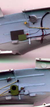 I
opted to leave the kit access doors in place, so I wouldn't have to go crazy
with cockpit detail. Not much can be seen unless one views it with a 1/48 scale
flashlight. However, I simulated fuselage structure with .010"x.030"
strip and used other strip stock and carved sprue for the various details. I
used a shortcut for the knobs, gluing in rounded bits of strip rod. Control
rods were added from .010" wire, and electrical wiring was done with armature
wire. More could have been done, but the detail is sufficient with the doors
in place. I painted the interior as per prototype practice: type 29 cockpits
were often painted the underside color. I used Polly S #500205 "topside
blue" and picked out details as shown in the illustrations, applying a
light wash of dark gray. After I closed up the fuselage I learned there should
be two metal oxygen bottles to the starboard side of and behind the seat. Oops.
I
opted to leave the kit access doors in place, so I wouldn't have to go crazy
with cockpit detail. Not much can be seen unless one views it with a 1/48 scale
flashlight. However, I simulated fuselage structure with .010"x.030"
strip and used other strip stock and carved sprue for the various details. I
used a shortcut for the knobs, gluing in rounded bits of strip rod. Control
rods were added from .010" wire, and electrical wiring was done with armature
wire. More could have been done, but the detail is sufficient with the doors
in place. I painted the interior as per prototype practice: type 29 cockpits
were often painted the underside color. I used Polly S #500205 "topside
blue" and picked out details as shown in the illustrations, applying a
light wash of dark gray. After I closed up the fuselage I learned there should
be two metal oxygen bottles to the starboard side of and behind the seat. Oops.
I trapped the cockpit floor and resin engine plate between the fuselage halves and glued the halves together. (On my sample, one port of the engine plate had to be enlarged to match the kit exhaust opening.) Once the glue was dry, I dry fitted the resin fuselage bottom to figure how best to glue it. I began with CA at the forward port joint, waited a few moments, and applied CA to the forward starboard joint. After a short wait, I ran a bead of CA where the flaps met the rear fuselage. On my sample, the resin lay a little high and I had to add a little putty to bring up the fuselage. The only other spot I puttied was at the very front, to continue the line of the stainless steel band. No putty was used anywhere else.
 I
painted the engine Polly Scale oily black and picked out the pushrods with aluminum.
Then I attached the engine to the resin engine plate with CA. Not much of the
engine is seen, so I didn't feel any more detail was necessary. I added the
tail surfaces and other kit parts, leaving off the landing gear and canopy.
I used CA to attach the resin cowl and cooling baffles. Remember, no wing guns
on the type 29. My particular aircraft was an early production type 29, which
had a square air scoop for the oil cooler. Later production aircraft used the
oval opening between cowl openings.
I
painted the engine Polly Scale oily black and picked out the pushrods with aluminum.
Then I attached the engine to the resin engine plate with CA. Not much of the
engine is seen, so I didn't feel any more detail was necessary. I added the
tail surfaces and other kit parts, leaving off the landing gear and canopy.
I used CA to attach the resin cowl and cooling baffles. Remember, no wing guns
on the type 29. My particular aircraft was an early production type 29, which
had a square air scoop for the oil cooler. Later production aircraft used the
oval opening between cowl openings.
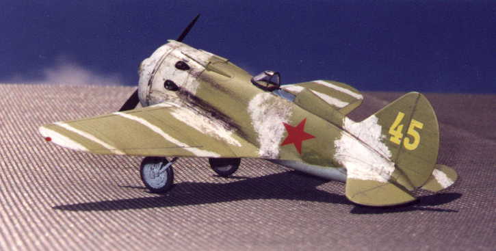
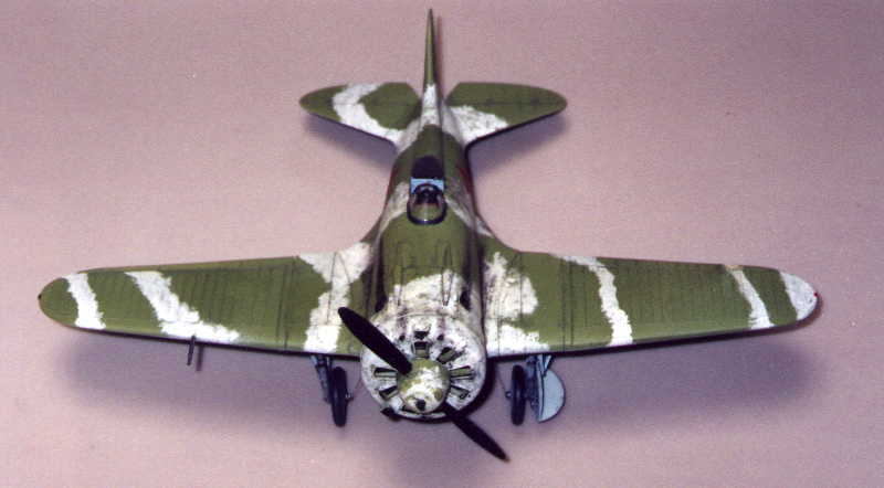
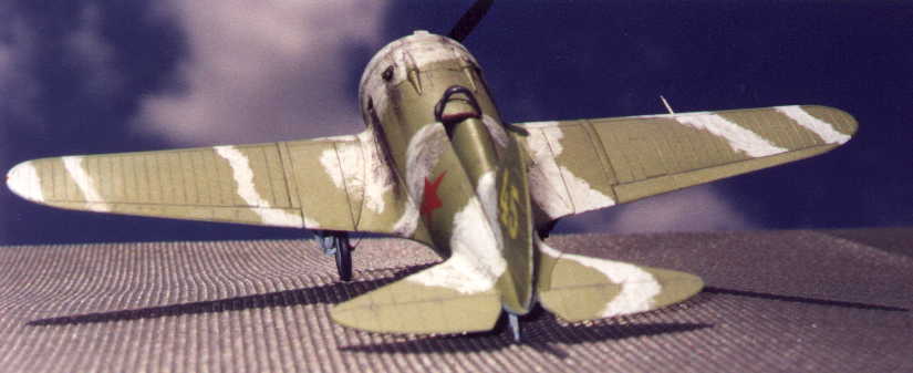
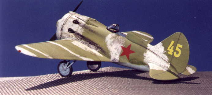
Time for paint. For my model, I chose a simple scheme of green over blue from the VVS Modeling Website. "Yellow 45" was illustrated using a single photograph showing mostly the port upper and side surfaces. The aircraft was camouflaged with white distemper and heavily weathered. My pattern for the distemper on the starboard sides is purely speculative.
 I
taped toilet paper around a 1/4" square strip of wood and inserted it into
the cockpit to both mask the cockpit and serve as a handle while painting. I
airbrushed the entire model with the underside blue color as a primer, to look
for flaws. Then I added a few drops of Polly Scale RLM 65 blue to the mix and
lightly shot the lower surfaces again. I then added a drop of light gray to
the mix and sprayed longitudinal streaks. I airbrushed the upper surfaces with
Polly Scale Warpac gray green (~FS34258), which may be a little light. No matter,
since I intended to model a weathered airframe. I then added Polly Scale US
interior green A/N611 (FS34151) and gave the upper surfaces a light overspray.
I then added a little mid green (FS34102) and streaked the upper surfaces. I
added to the weathered effect with washes and drybrushing with grays and greens.
Note that the starboard aileron has very little weathering, simulating a replacement
part.
I
taped toilet paper around a 1/4" square strip of wood and inserted it into
the cockpit to both mask the cockpit and serve as a handle while painting. I
airbrushed the entire model with the underside blue color as a primer, to look
for flaws. Then I added a few drops of Polly Scale RLM 65 blue to the mix and
lightly shot the lower surfaces again. I then added a drop of light gray to
the mix and sprayed longitudinal streaks. I airbrushed the upper surfaces with
Polly Scale Warpac gray green (~FS34258), which may be a little light. No matter,
since I intended to model a weathered airframe. I then added Polly Scale US
interior green A/N611 (FS34151) and gave the upper surfaces a light overspray.
I then added a little mid green (FS34102) and streaked the upper surfaces. I
added to the weathered effect with washes and drybrushing with grays and greens.
Note that the starboard aileron has very little weathering, simulating a replacement
part.
Once I was satisfied with the weathering, I applied the winter distemper camouflage. I used Delta Ceramcoat acrylic white. I did not feel airbrushing would yield the results I wanted, so I drybrushed the white. I followed the pattern shown on the VVS website illustration for the port side and applied a similar pattern on the starboard side. Again, no distemper was applied to the starboard aileron, emphasizing the idea of a replacement part.
 Once
I was satisfied with the distemper finish, I airbrushed the entire model with
Future floor polish. When this dried I applied the decals. While there is nothing
wrong with the kit stars, I used some from the spares box which were a darker
red. I preferred the look of the darker red against my weathered finish. The
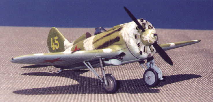
actual sheet used was from LTD's LaGG-3. The yellow "45"s were provided
by Erik Pilawskii, who made them with an ALPS printer. I first had to apply
white "45"s and when dry airbrush the vertical tail with Future. Then
I added the yellow "45"s and when dry airbrushed with Future once
again. The ALPS printed decals tend to be very fragile, so I opted to apply
maximum protection. I airbrushed a final coat of Future over the entire model.
Once the Future was thoroughly dry, I made up a thin enamel wash of darkish
gray/green and picked out panel lines. I prefer a more subtle depiction of panel
lines than the normal black, as I feel it renders a better scale appearance.
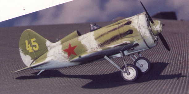
The exhaust and gun stains are a mix of brown, dark gray, and black pastel chalks
applied with a sponge mascara applicator. Don't forget exhaust stains on the
gear doors, if you are using them. A final coat of acrylic flat clear finished
the painting stage.
Once
I was satisfied with the distemper finish, I airbrushed the entire model with
Future floor polish. When this dried I applied the decals. While there is nothing
wrong with the kit stars, I used some from the spares box which were a darker
red. I preferred the look of the darker red against my weathered finish. The
actual sheet used was from LTD's LaGG-3. The yellow "45"s were provided
by Erik Pilawskii, who made them with an ALPS printer. I first had to apply
white "45"s and when dry airbrush the vertical tail with Future. Then
I added the yellow "45"s and when dry airbrushed with Future once
again. The ALPS printed decals tend to be very fragile, so I opted to apply
maximum protection. I airbrushed a final coat of Future over the entire model.
Once the Future was thoroughly dry, I made up a thin enamel wash of darkish
gray/green and picked out panel lines. I prefer a more subtle depiction of panel
lines than the normal black, as I feel it renders a better scale appearance.
The exhaust and gun stains are a mix of brown, dark gray, and black pastel chalks
applied with a sponge mascara applicator. Don't forget exhaust stains on the
gear doors, if you are using them. A final coat of acrylic flat clear finished
the painting stage.
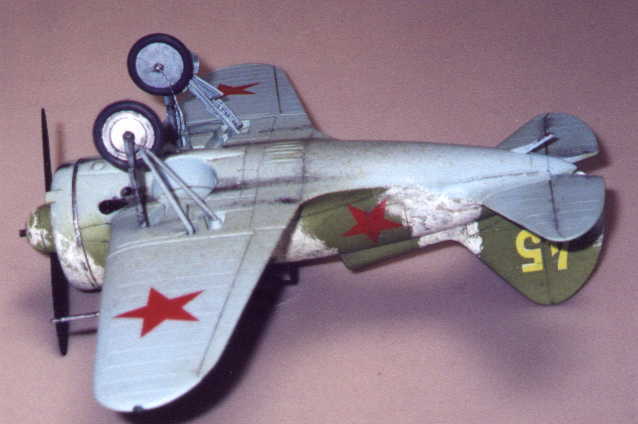
 While
waiting for other subassemblies to dry, I worked on the landing gear. The port
gear, wheel, and doors were finished in the underside blue color. The starboard
gear was finished in RLM 65 blue to represent a replacement unit, and the wheel
was finished in aluminum. I do not care for the I-16 gear doors, and I intended
to finish my model without them. However, since this is a review of the resin
set, I decided to model the port gear doors to show how the parts look in place.
After painting them underside blue, I airbrushed them with Future and applied
a dark gray enamel wash. The wash was also applied to the struts. Once the landing
gear struts were attached with CA, I added hydraulic lines using armature wire.
I attached the gear doors with white glue so I could remove them later. Gear
door actuators were added using .010" brass wire. At this point I glazed
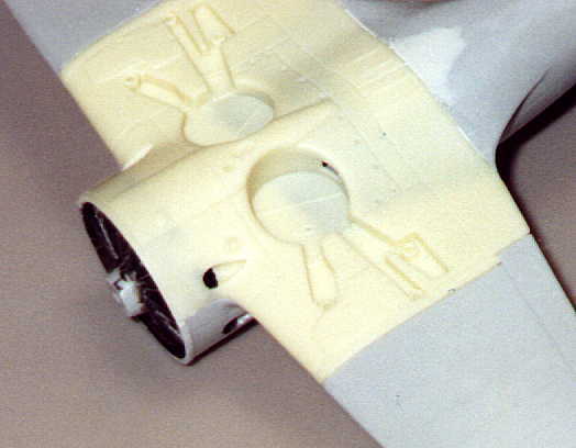
the starboard gear well window with white glue. The I-16 landing gear was retracted
by wire. So I drilled into the oval-shaped opening near the centers of the wheel
wells with a #77 bit and added the retractor wires using invisible thread, painted
with Polly Scale steel.
While
waiting for other subassemblies to dry, I worked on the landing gear. The port
gear, wheel, and doors were finished in the underside blue color. The starboard
gear was finished in RLM 65 blue to represent a replacement unit, and the wheel
was finished in aluminum. I do not care for the I-16 gear doors, and I intended
to finish my model without them. However, since this is a review of the resin
set, I decided to model the port gear doors to show how the parts look in place.
After painting them underside blue, I airbrushed them with Future and applied
a dark gray enamel wash. The wash was also applied to the struts. Once the landing
gear struts were attached with CA, I added hydraulic lines using armature wire.
I attached the gear doors with white glue so I could remove them later. Gear
door actuators were added using .010" brass wire. At this point I glazed
the starboard gear well window with white glue. The I-16 landing gear was retracted
by wire. So I drilled into the oval-shaped opening near the centers of the wheel
wells with a #77 bit and added the retractor wires using invisible thread, painted
with Polly Scale steel.
Now came a tricky part. I had prepared the exhaust stubs by painting them Polly S boxcar red, washing them with black, and drybrushing with rust. I cut the stubs from their pouring block and attempted to attach them with white glue, only to find them a little too big for the openings. Ah, the wisdom of dry fitting. I had to trim down the stubs, particularly the paired units, to fit into the openings in a realistic manner. It was but a minor setback and nothing the average modeler cannot handle with a little patience.
 As
stated before, my resin set did not have the propeller blades. I had painted
the spinner as I painted the rest of the airplane, so now I had to fit the kit
prop into the resin spinner. It was a simple matter of marking a center point
and tip points on a piece of paper, cutting the prop at the "collar",
and trimming with a hobby knife until the blades fit into the spinner's openings
and the center point and end points lined up with the marks on the paper. I
used white glue to attach the blades so I would have time to adjust the pitch
of the blades. I painted the blades flat black with a little aluminum on the
leading edges to simulate wear.
As
stated before, my resin set did not have the propeller blades. I had painted
the spinner as I painted the rest of the airplane, so now I had to fit the kit
prop into the resin spinner. It was a simple matter of marking a center point
and tip points on a piece of paper, cutting the prop at the "collar",
and trimming with a hobby knife until the blades fit into the spinner's openings
and the center point and end points lined up with the marks on the paper. I
used white glue to attach the blades so I would have time to adjust the pitch
of the blades. I painted the blades flat black with a little aluminum on the
leading edges to simulate wear.
At this point I worked with the canopy. It would be preferable to "heat squish" a new one from clear stock, but I elected to use the kit part, which is overly thick. To lessen this thick appearance, I carved down the trailing edge with a hobby knife until it looked thinner. Then I hand painted the frames, cleaned up my stray paint with a wooden toothpick, and attached the canopy with white glue. The I-16 had a leather pad at the front of the cockpit opening which I simulated with a piece of .015"x.040" strip, cut to fit, rounded, and painted boxcar red.
 Final
details amounted to adding the kit pitot tube, painted steel, and the wingtip
lights, painted RLM 23 red (port) and FS34102 green (starboard), each coated
with future.
Final
details amounted to adding the kit pitot tube, painted steel, and the wingtip
lights, painted RLM 23 red (port) and FS34102 green (starboard), each coated
with future.
I found the Airwaves I-16 type 29 conversion set to be a wonderful fit overall and a pleasant modeling experience. No major obstacles were encountered and I feel most modelers of average experience can use this set, even as a first time conversion. I am most satisfied with the results.
I would like to thank Matt Bittner, Erik Pilawskii, and Peter Vill for their assistance in this project. I found the VVS Modeling Website, run by Messrs. Bittner and Pilawskii, an invaluable resource for this project. There is a link there for a New Zealand website which has numerous pictures of recently rebuilt I-16s, recovered from the former Soviet Union. And I apologize to Mr Vill. He asked me for a brutal review, pulling no punches. Sorry, I found nothing major to pick on. Minor quibbles are as noted.
 |
 |
 |
 |
 |
 |