Academy 1/48th Polikarpov I-16 Type 24
By Hector Mirasol
Academy 1/48th Polikarpov I-16 Type 24By Hector Mirasol |
|
Modeling the I-16 is always a challenge, and because of many different reasons. There is only one reasonable kit in 1/48 scale, and to get accurate information on the subject has always been hard.
There were several Types of I-16 built since its first appearance in 1934. The first series were the type 4 and the last the Type 29 . Between these were Series 5, 6, 10, 12, 17, 18, 24, 27 and 28. The differences between the series have been subject for much debate and speculation. I have been reading and researching about the I-16 for years and I have encountered many contradictions between the different sources . The first widely available monograph on the Polikarpov fighter was published by Squadron Signal, then several articles were published in different magazines. Recently the most complete ( and accurate) monograph on this revolutionary aircraft was published by Armada and it is in Russian so I could only look at the drawings and photographs, hardly concealing my despair. Since last summer two different books were published in France, and after reading them I can say I was pleased. They have pictures that I have never seen before and a few nice profiles but, still questions regarding some important differential details between series could not be answered .
When I meet Erik Pilawsky about one year ago, he enlightened me about many things on the I-16 (but not only about the I-16) . Even though there were still some dark areas (not just the exhaust), again Big Erik came to the rescue and sent me some preliminary work he is doing on the subject, and believe me, after that, only the number of rivets shall remain a mystery. You will see it soon , so I shall not say anything more about it.
So far, the only reasonable kit in 1/48 scale is the Hobycraft one. Now the same kit is marketed by Academy, but the molds are the same. On the several types of Hobycraft kits the only real differences are the wings and a few extra small details. In the box, the Type 5 had a different wing upper surface with less ribs and leading edge reinforcement which is placed much forward than older newer types. It also gives you a different windscreen of triangular shape which slides to close or open the canopy. There is also a tail skid and an early type of propeller hub (more pointed).
The Type 10 kit will give you a different upper wing surface, front cowling,
wheels, more rounded windscreen, and that is all. The late types will vary in
the propeller hub, tail wheel, rocket mounts, front cowlings, different wing
armament (machine guns or large barrel gun) a nose lower air intake, maybe a
radio mast or a camera emplacement, etc. And there is a version that will
include skis.
Basically the fuselage, the cowling side panels and the number of exhaust ports,
and the small door access to the canopy are the same; and therefore wrong. The
Academy kit is the same mold and gives you in the same box all the different
bits with the late type wing. That gives you more choices but also the same
errors.
The shape and dimensions of the kit are basically correct and once done it gives you a beautiful small fighter which resembles the original one. But if you want the real thing, you have to be prepared for a bit of extra work. Bob Partridge did recently an excellent article published on this site about the Type 5 were you can find in detail all you need to make a beautiful l and accurate model.
In this article I am going to describe how I used the Academy kit to build
a Type 24.
A Few Historical Notes
The Type 24 was an I-16 frame fitted with a new development of the Shevetsov M-62 engine, which had the designation M-63 . The new engine could manage 900hp at 4500m.
In August 1939 , test pilot A. Nikashin flew the Type 24 prototype for the first time. The plane showed the best performance ever of the already extensive Ishak family (Soviet pilots called their I-16s "donkey" affectionately). Maximum speed at sea level was 440 km /h and 489 at 4800m . A full throttle climb to 5000 was done in 5.2 mins and the service ceiling was at 10800m. The Type 24 was the most produced variant from 1940.
Apart from the improved engine, other changes were made. The plywood skinning
of the upper wing leading edge was improved. A radio compartment was introduced
, with an access hatch on the starboard side. Also on the starboard side a second
small access door to the cockpit was fitted. There was often a gun camera emplacement
at the top of the fuselage, just above the canopy. Two 70 Kg fuel tanks could
also be fitted under the wings and the tail skid was replaced by a small wheel.
But the most important improvement was to be on the surface finish. In spite
of all those improvements to the prototype, production planes did not change
much in performance, mostly because the wrong type of propeller was chosen for
the serial production planes, with a gain in weight and fuel consumption. A
total of 934 Type 24s were built between 1939 and 1941.
Modeling the Type 24
The Interior
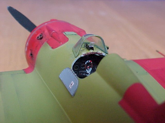
Forget about all parts in the kit. The instrument panel is very nice but probably too big, and if you fit it as per the instructions there is not enough room between the instrument panel and the cockpit floor. Basically, there two possibilities: you scratch the whole thing, or you buy the Eduard Photo-Etched set. I used mostly parts from the set and scratched the rest.
The control column from the kit is one of the oddest bits I have ever found in a kit box, and I still dont know what are you supposed to do with it. I made mine with plastic and the brass PE set handle, adding wires of stretched plastic. The seat could be used as a base if you want to re-shape it. The nice Photo-etched set from Eduard is strongly recommend if you dont fancy to scratch build the whole thing.
I chose to scratch build all the internal structure because I think that when using plastic the effect is more realistic than with the flat Photo-etch . First, I sanded down all the inside of the kit and then used plastic rods for the tubing. The frame of both doors has a rectangular section, so I sanded down the plastic rod until I got an appropriate finish. I also cut out the two small access doors and glued one closed and the other open (which will facilitate to have a look at the inside when the model is finished).
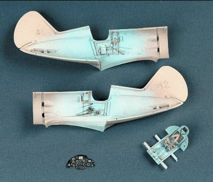
fig1 , interior, seat and instrument panel
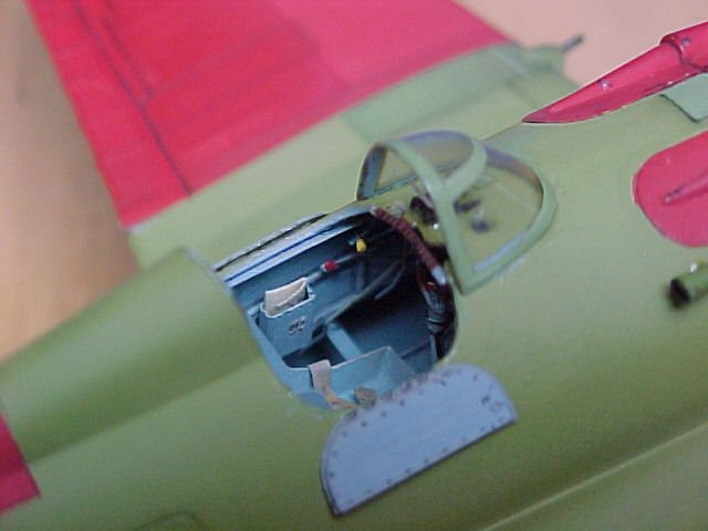
Then I used the side consoles, levers, map box, and bits and bobs given in
the set together with some scratch-built itmes (including a small folded map,
I had to mention it) and wiring done using stretched plastic sprue.
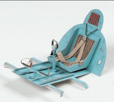
Fig2 . seat
The cockpit floor, ruder pedals, seat, instrument panel and harness are from the Photo-etched set with a few modifications. The bulkhead behind the seat is also from the Eduard kit. I will discuss the painting later on.
The etched instrument panel is very nice, indeed, and will look very convincing
if properly painted. Normally, these were black and I choose to weather it with
a dry brush and highlighted the dial roundel with toned down silver and black
around the outside. I have to say than the picture is much bigger then the instrument
the panel itself and looking at the real thing it does not look so weathered.
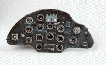
Fig. 3 instrument panel
Detailing the Fuselage
When all the interior is done, one can glue both halves of the fuselage together.
At this stage, with just the fuselage at hand, my advice is to do some detail
work to improve the kit.
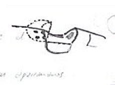
Fig 4 , drawing canopy
Two small circular openings are located on the top of the fuselage to facilitate
light getting in the cockpit. Before drilling them, be sure that you locate
them conveniently and dry fit the canopy on top.
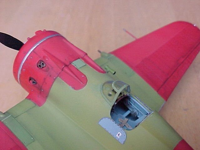
Also, I decided to inscribe all rivet lines on the cowling lateral panel. I
did them using a very small drill and doing very superficial holes on the plastic
surface for the big rivets. The best thing to do for the very fine ones is using
a metal ruler and a small blade from a circular saw (which I did not have).
First you draw the line were you want the rivets to go, then you put the ruler
or a flexible band of brass for curved surfaces and then you inscribe the holes
rolling the circular saw thing in just one go. It is best to put a bit of tape
where you want the line to finish, and so protecting the surface and ensuring
that you will not end with rivets all over the place .
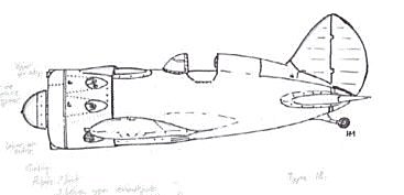
Fig 5 . Drawing profile
On top of the fuselage there are two lumps (part #20) which are the access to the nose machine guns. I also detailed them and inscribed a few rivets. The line between the cowling panels and the fuselage was quite a marked one on the real plane, so I deepened it considerably using a inscriber.
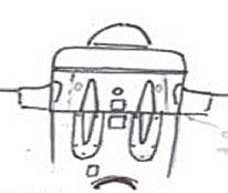
Fig. 6 Drawing cowling
The rectangular panels had a rounded end, were part #20 is to be glued, and are made of thin metal plate .
I also inscribed some rivets at the root of both horizontal stabilizers, the spinner, and the panels that support the tail fin.
Now the interior is finished and both halves of the fuselage glued together (with all additional details done). It is time to prepare for the wings.
Part C1 in the kit its the bottom half of the wings, fuselage and nose. Several modifications will need to be done.
I have done quite a few I-16s before, and depending on each particular kit,
at times the dihedral angle of the wings once the model is finished is not quite
right. According to the drawings, the upper wing surface is at a 90 degree angle
with the midline of the fuselage. The lower wing surface is V shaped if you
look at it from the front. Once it is finished the visual effect is that the
wing tip is a bit lifted upwards, and unless you shape the wings on the finished
model, sometimes it will look quite the opposite (and that really gets me).
To avoid (or prevent) that from happening, I have a trick. In the middle of
part C1 are the wheel bays. They are quite deep and cumbersome if you look at
them from the inside. The plastic wall in between both bays is quite thick.
With a thin saw I cut a section of about 2mm at the bottom and 3mm at the top,
being careful not to go through. After doing so, I dripped some SuperGlue in
the fissure and then kept it in place until it dries. That will give the wings
that subtle dihedral look that they have to have.
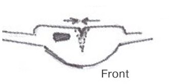
Fig 7 wheel bay front drawing
Also at this stage I opened the small window on the back wall of the starboard wheel bay. The purpose of this was to work as a wheels down indicator: when the landing doors opened, light will come into the cockpit from below. Also, a very small hole has to be drilled on the bay bottom to get the landing gear retracting cable through.
Other area that needs work is the lower exhaust openings. There were two outlets with double exhausts on each side. The location is wrong. Looking at pictures of the aircraft it is clear that these are higher and also quite near to the lower aspect of the wing root. This means that first you have to use putty to cover the exhaust ports and, once really dry and hard, drill the new ones in the right position. Once the new ports (of the same shape) have been done, the next problem is that you need a concave inner surface. Again, I did that by molding it with epoxy putty and let it dry. Sanding and adjusting (a tedious task) will be necessary to get the right shape. I then gave several coats of SuperGlue to harden it, and drilled two holes in the place that the exhausts will come out.
The Wings
Now it is time to glue both wing surfaces together and the glue them to the fuselage. These fit without too much pain, and only a small amount of filler and sanding is required. At any stage, I warmly recommend plenty of dry fitting; in fact, I do that at every stage of the building.
You can see now more or less the general shape of your MOSCA (as we Spanish like to call it). If you look at the wing surface now you may be pleased. Or you maybe not. I wasnt. I wanted to improve the wing surface, and as my friend Bob Partridge has done, I came up with system using Tamiya masking tape
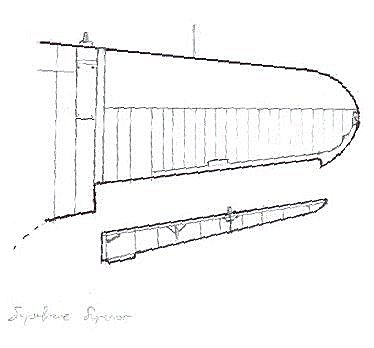
Fig 8. Drawing wing
If I am not wrong, the front part of the reinforced wing surface was ply sheet, and then came the ribs with the fabric covering. The rib structure is raised on the kit, but starts too far forward. I sanded down the excess, protecting the rest with thick tape. Incredibly (Bob had the same problem), after sanding the raised lines had become engraved lines! I used again SuperGlue to cover them and sand it again until having a completely even surface (do not trust your eye: when you are happy, spray a thin coat of primer to ensure it is O.K.).
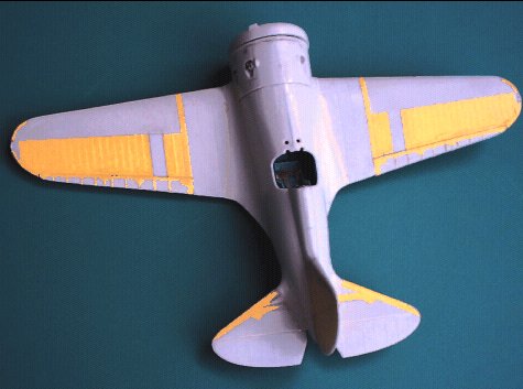
Fig 9 construction upper view
I then covered the rest with the masking tape. Because the raised ribs are
underneath, the effect will look most convincing. After covering the main surface,
I cut small strips of tape to represent other details as seen on the drawings.
I also cut down the ailerons and used the same technique.
With the fin and stalinizers (whoops, that was a Lapsus mentis)--stabilizers,
I meant--I used the same process. Before gluing the stabilizers I brought
down the elevators (as it is shown on many I-16 pictures on the ground).
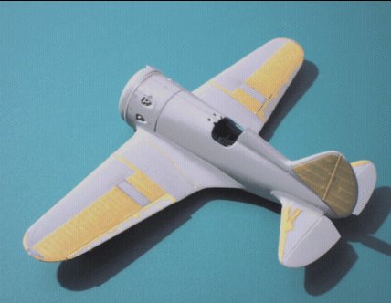
Fig.10 Construction upper /side wings & tail
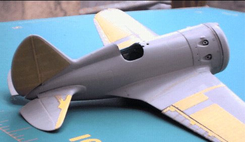
Fig . 11. Construction, starboard
A similar operation is needed on the lower surfaces , but the surface covered by the tape is larger and starts closer to the wing edge
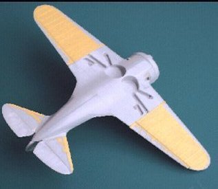
Fig 12 Lower surfaces, construction
Engine and Cowling
The engine provided in the kit is quite acceptable, considering that you are hardly able to see it once it is in place, and then only if you decide to keep the cowling shutters open. If you really want to open up any panels to show a proper engine, then you must buy the Neomega Resin engine. Neomega has crafted a real resin jewel. It is a fine reproduction of the Shevetsov M-63. It gives you everything you need, apart from the engine frame which is easily done with plastic tube. It includes the cylinders, the block of the engine, carburetor, supercharger and the exhaust. It is so nice, that it is even worth whole to buy it so as to display it at the side of your model.
I have enclosed a couple of pictures of the engine that I did in a different I-16 project, a Type 18 that I regret has few errors (that is the bad thing about improving your knowledge, realizing how ignorant you are).
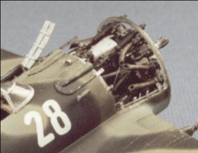
Fig 13 Engine from white 28
The cowling is a very characteristic part of the I-16, and it will help us to identify the type. The number and location of exhaust will vary depending on the type, and also the air intakes and location of the armament.
The kit gives you a front cowling with two openings for the machine guns and a triangular air intake at the top. The gun muzzles should protrude from the cowling rather than being just two holes; this is easy to do with two small tubes of plastic or metal.
The etched set gives you the shutters and an additional part to represent the back of the cowling shutters. The lower air intake should be (we now know) an upsidedown T, and can again be improved with the PE set.
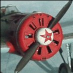
Fig. 14 finished cowling front view
Landing Gear
The landing gear on the kit is quite acceptable, but I couldnt resist to improve it a bit. The doors are from the etched set, and the wheels are from the kit, but sanded down flat where they touch the ground and given a loaded appearance with some milliput.
As I said before, is necessary to drill a small rectangular window on the posterior wall of the starboard wheel bay and then cover it with a small piece of acetate, or clear platic card.
The wheels have metal tensor wires that came from the wheel bay in a slightly eccentric position.
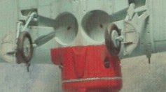
Fig 15 , wheel bays finished
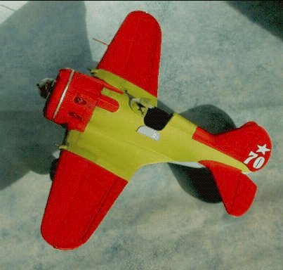
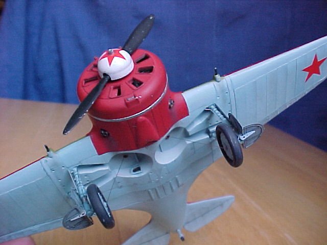
Painting: I-16 "White 70"
When I decided to do yet another I-16 I asked Erik Pilawskii for some suggestions. In no time he came up with a picture of the Naval ace Alexei Denisov in front of his Type 24 with a very unusual camouflage scheme of Green AII, red nose, wings and tail, a white "70" with again a white star on the fin, and a white spinner with a red star. That was it!
Alexei Denisov flew in the Spanish civil war in the Teruel front under Devotchenko, managing to get 7 victories. When back to the Soviet Union he was involved first in the Winter War, and finally in the Great Patriotic War. When flying "White 70" he was the Commander of the 12 OIAE (Independent Fighter Squadron) and later with the 13 IAP KBF (4 th Eskadrilya).
Before painting the plane I applied a coat of gray primer to be sure that everything was in order, and to improve the paint adherence to the model. Once the primer coat was dry, I sprayed first the lower surfaces with underside Blue AII . I always give at least 3 coats, quite thin, and then I re-spray in selected areas with different shades of the same color taking in to account which panels will weather more than the others, where stains are likely to be, and where dirt is going to accumulate. I will mask the area with masking tape or Post-it notes, and always using very thin paint and subtle coats. If the effect is not what you want, you just do it again. I used what was left of my Aeromaster stock (now completely gone, and in fact I had to mix some paint from different sources to finish the job).
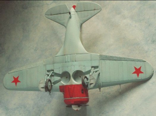
Fig 16 Lower view, White 70
Now it is time to do the upper surfaces. To spray the Green AII, the first problem was to get the appropriate shade. My friend Pete Vill was kind enough to give me a chip of the color, and I worked mixing acrylic paint from different sources .The closest paint that I could find was from Wargamer (Camo green). It is quite close but a bit too yellow and light. I added a small amount of a deep green and medium gray until I got the desired shade, then thinned it down with distillate water and sprayed it as I did the underside surfaces, making subtle differences between panels.
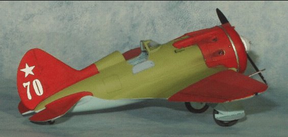
Fig 17 White 70 starboard
Then it was the reds turn. Again I did a mixture of red: Carmine and Vermilion (Deep red). I used an acrylic paint from a Spanish brand called Vallejo . The process was again the same.
Finally, I had to deal with the white star and "70". Obviously I had no decals for them, so I used transfers from a Soviet Tank set from Verlinden. The numbers were not exactly the right shape so I modified them with a brush and white paint. There are red stars on the wings undersurface.
Weathering
Painting and weathering is what I enjoy most about modeling, probably because I can see the plane already. The first step is to work on the panel lines. The panel has already a subtlly different shade. Now I mask the panel line very carefully leaving the engraved line "exposed" to the airbrush. With an extremely thinned down paint and low pressure on the compressor, I work on the panel line. Because there is masking only to the outer limit of the panel, the line there will be hard. But, because on the line inside there is no mask, the effect here will be soft and gradual. I work in this way on individual panels. Once the job is done, I paint free hand with an even more thinned-down paint (this time dark brown or dark gray). I gave several very subtle touches were I feel it looks pertinent, trying to achieve a visual effect rather than anything else.
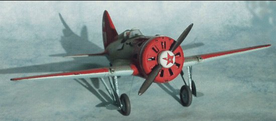
Fig 19 White 70 front
Once the general paint has been weathered, is time to work on more specific areas. First, the undercarriage; adding dirt and oil stains were appropriate. A very subtle jet is sprayed coming out of air outlets using a mixture of black and brown. On the top surface I worked mostly on the exhaust fumes and chipping the metal panels and propeller .
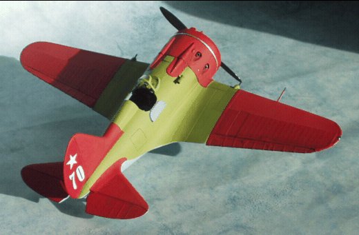
Fig 20 White 70 rear/starboard
The exhaust stains were done using black, gray and brown (in that order), always trying not to do it too heavily (particularly on this aircraft, which was, by the look of the picture I have of it, quite well maintained). To represent small chips on the paint over metal parts I do it with a very sharp brush, first making a small black irregular dot and the inside of it I paint it silver. The size has to be small and again the effect has to be subtle. It is also important to think where are you going to chip the paint, considering which are the most exposed areas or where the maintenance work will affect it more.
References.
Erik Pilawskii. From his still unpublished but very much awaited works.
M. Maslov. Polikarpov I 16 . Armada. (2) ( Russia)
Christopher Cony, Michel Ledet, J.Arraez Cerda et alt . Collection Profils Avions
n4.( France)
Pilokarpov Fighters an action Pt 2 . Squadron/Signanal publications. N 162
J.Miranda P. Mercado. Aviacion Mundial en Espana .Aviones Americanos y Rusos.
1936'1939
Ed. Silex.(Spain)
J. Arraez Cerda. LAviation de Chasse de la Republique Espagnole. Hors Serie
Avions n 3. Ed Lela Presse ( France)
C. F. Geust et alt: Red Stars , Soviet Air force in WW2 . Ar Kustannus
Oy (Finland)
Y.Gordon D. Khazanov. Soviet Combat Aircraft of the WWII .Midland Publishing
Limited. UK
Special thanks to my friends
Pete Vill, Erik Pilawskii, and Bob Partridge