The Contrail kit has been around for at least 12 years and, despite its age, is reasonably accurate.
Although it is now no longer available, I purchased mine about 10 years ago and it has been on my list of models to make for all that time, but it wasnt until a recent issue of the Russian magazine M-Hobby arrived that I took it out of its box and looked at it again.
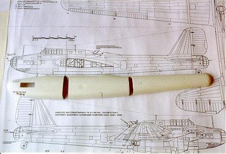
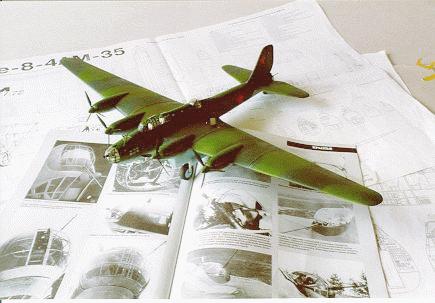
After cutting the parts from their backing sheets, I placed them over the 1:72 scale plans that are included with M-Hobby and was reasonably satisfied with the overall shape. The most glaring error however, is the fact that the fuselage is about 1 ½ inches (38mm) too short !
Given that the master was probably made about 15 years ago when accurate data was hard to obtain, the then owner of Contrail, Gordon Sutcliffe - assisted I think by Harry Woodman, has made a very competent job of capturing the lines of this large four-engined Soviet bomber very well indeed.
The M-Hobby magazine is highly recommended for anyone attempting the Contrail
kit and can be obtained from Linden
Hill Imports .
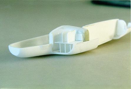
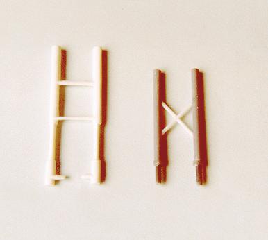
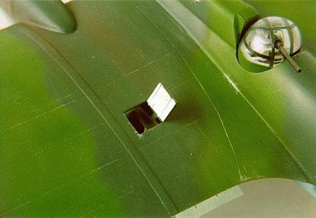
To lengthen the fuselage, I made two cuts in the port fuselage half - one just behind the cockpit and another just forward of the rear crew entry door - see Photo 1.
I also cut out a large aperture to take the side window glazing and, after trying to cut out the individual windows for the bombardiers station in the nose, I cut away the whole area of the glazing. I later carved a master for the nose glazing and plug moulded a replacement part.
Deciding to go the whole hog, I also cut out the bomb bay doors, the nose and tail turret apertures, the small windows in the fuselage and the cockpit opening.
The three port fuselage sections were placed over the scale drawings to get the correct length and short lengths of scrap plastic card were cemented on the inside of the fuselage to join the sections together. The fuselage outer skin was made good by cementing scraps of plastic into the joins and blending it all in with filler.
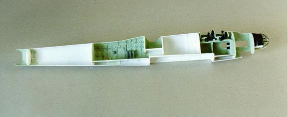
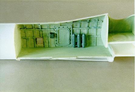
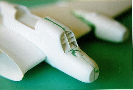
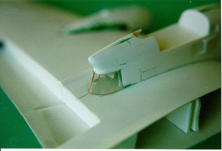
Once I had a complete port fuselage half of the correct length, I added detail to the cockpit area, rear fuselage opposite the starboard entrance door and the navigators compartment - See Photos 2 & 3. To strengthen the rather fragile fuselage, I added a few bulkheads, shelves for the mid-upper, nose and tail turrets to rest on plus a roof and forward and aft bulkheads for the bomb bay.
The pilots cockpit area was detailed using the M-Hobby plans and photos and includes the two seats in tandem, control trim wheels made from pop fasteners, control columns constructed from short lengths of sprue with a semi-circular wheel from a cut-down pop fastener added to the top, rudder pedals, scratch-built instrument panels and various ribs, stringers and boxes - Photo 4.

The areas of the interior that would be visible was painted with Humbrols 122 to represent the Soviet pale green as recommended by the guys from VVS. The vacform turrets provided by Contrail are OK - but nose and tail turret glazing didnt match the mouldings for their solid backs - so the backs had to be modified to fit the clear parts. After detailing the interiors, but leaving off any guns, they were offered up to the port fuselage half for a test fit. I then discovered that both the front and rear turrets were slightly wider than the surrounding fuselage.
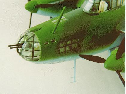
The nose & tail turrets were cemented in place and tabs of plastic card were added to the fuselage along all the joints to strengthen them and the three sections of the starboard fuselage were cemented in place with their gaps being filled in the same manner as the port fuselage. The gaps at nose and tail made by the over-wide turrets were filled with scraps of plastic card and the completed fuselage had all its joints filled and sanded smooth. Clear plastic panels were let into the nose and the gaps made good with filler. This large glazed area would later be masked off and painted to represent the multiple windows on the Pe-8 - see Photo 5.

The kit wings are simple upper and lower surfaces. The trailing edges were rubbed down to wafer thinness and the flap areas cut away. Two spars, made from thick plastic card, were added to each wing - spaced a few centimetres apart. This gave strength to the wings and provided a channel into which another spar, this time slotted through the fuselage, would later fit. The flap areas were boxed in with scrap plastic card and a rectangular hole was cut into the port upper wing surface where the nacelle gunners hatch is located. Because the Pe-8 has such an unusual arrangement of gun turrets in the rear of the inner engine nacelles, I wanted to show off the access hatch and the internal detail. The gunner gets in through the upper hatch and descends through the wing into his turret, so some wing ribbing and spars were added to the port wing interior and a hole corresponding to the turret was made in the lower wing surface.
The upper and lower surfaces were cemented together and the wingroot was rubbed down until it made a snug fit up against the fuselage. A slot had already been made in the fuselage (not shown in the photographs !) And two bulkheads had been added - again spaced a few centimetres apart. This arrangement allowed me to make a short spar, with built-in dihedral and slide it through the fuselage slot. The spar extended to about the outer engine nacelles and provided both strength and dihedral to the wings. The spar was cemented in place in the fuselage and the wings were slid over it to butt against the fuselage. Another spar, this time made from plastic rod, was added going through the fuselage and into the wing roots at their trailing edges. This rear spar ensured that the wings adopted the correct angle of incidence and further strengthened the wing-to-fuselage join. I didnt cement the wings in place at this stage, figuring it would be easier to add and rub down the engine nacelles with the wings separate from the fuselage.
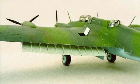
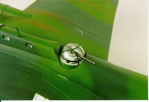
As well as the previously mentioned gun turrets, the Pe-8 also has an unusual arrangement for the coolant radiators. To minimise drag, the radiators for both inner and outer 1340 hp Mikulin AM-35 liquid cooled inline engines are housed in the inner nacelles only. The radiators have clamshell shutters and Contrail provide a moulding to represent the radiator core for both nacelles. I decided that I would make my Pe-8 showing one engine with the shutters open to show the interior detail and one with the shutters closed - OK call me lazy !
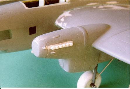
The engine nacelle parts were cut from their backing sheet and rubbed down. The openings for the wheel wells were cut out and the wells boxed in. The radiator opening were cut out and the moulded radiator parts added to one nacelle. Although it fits quite snugly, the moulding is not completely accurate. Photographs in M-Hobby show that there is a central vertical divider with three horizontal baffles on the left and two baffles on the right when viewed from the front, so these were added from scrap plastic card. Plastic card with hatching scribed onto it was also used to replace the moulding of the radiator matrix, which isnt very well defined - see Photos 6 & 7.
The moulded exhaust shutters on the nacelle behind the radiator were opened up on this nacelle - they were left closed on nacelle with the closed intake shutters.
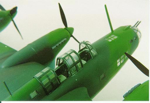
The glazed areas at the rear of the nacelle were cut away and after some detail had been added to the gunners compartment in the form of a seat and ammunition boxes, the completed nacelle was cemented in place onto the wing leading edge. Glazing was added to the rear of the nacelle using quite thick clear plastic sheet carefully bent to shape using a paper template to get the correct shape - see Photo 8.
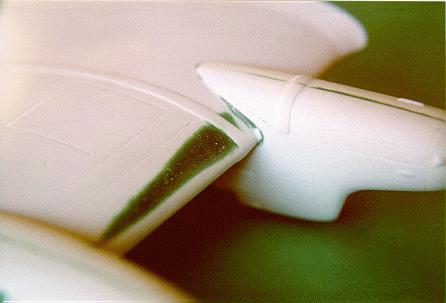
A couple of areas along the wing leading edge needed attention with the filler where the wing profile is poorly moulded - see Photo 9. With all four nacelles added and their join lines filled and smoothed down, the wings were finally cemented to the fuselage and the joint made good with filler.
The tailplanes were added with plastic rod spars for strength and the whole
model was rubbed down, washed in warm soapy water and, when dry, given a coat
of grey primer to show up any flaws in the joints.
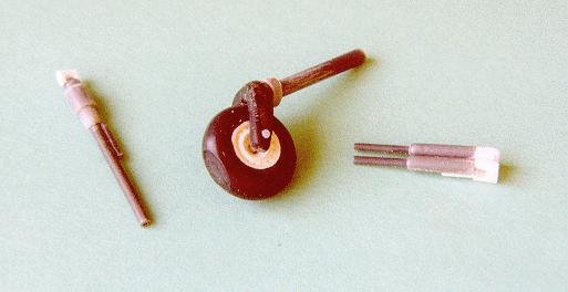
The undercarriage mainlegs supplied as injection mouldings by Contrail are completely inaccurate, so new ones were made using varying thicknesses of Contrail rod and sprue - see Photo 10. The kit wheels are the correct diameter and were used but I rubbed them down and added new wheel hubs using discs of thin plastic card. They will eventually be replaced with correct items from the Equippage range of wheels.
Contrail supply additional mainwheel doors so you dont need to use the ones cut away from the nacelle moulding. The injection moulded tailwheel was unusable, so a scratch built replacement was made using a Phantom mainwheel, scrap plastic and rod. The twin 7.62mm ShKAS nose and single nacelle machine guns plus the 20mm ShVAK cannons were scratch built from rod and scrap plastic - see Photo 11.
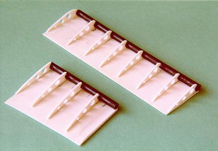
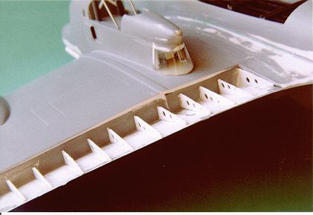
The flaps that had been cut away from the wing underside had rib detail added from plastic card with lightening holes drilled in them - a daunting task scratch-building so many. Corresponding ribs were also added to the flap cutaway area on the underside of the wings. Plastic rod was applied to the leading edge of the flap and the two sections of flap were cemented to each wing underside - see Photos 12 & 13.
The engine exhaust stubs supplied by Contrail are completely inaccurate and need to be replaced with scratch-built items. I simply took a thick section of plastic card, rounded off one edge to a semi-circular section and then made saw cuts into the edge to represent the stubs. Once cut away from the plastic card sheet and cleaned up, they were cemented to the nacelles.
Note that on the M-Hobby drawings, all 4 engine nacelles have five exhaust stubs - four small and a larger (presumably double one) at the rear - except for the OUTER stubs on the INNER nacelles - they have a more normal arrangement of six individual stubs - see Photo 14.
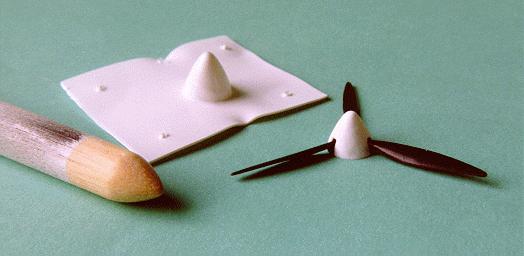
The kit-supplied props are almost unusable, so I replaced mine with blades from a Lancaster kit added to home-made spinners. The kits outer nacelles are slightly narrower than the inners - a moulding fault, not my rubbing down ! As a consequence, two different sizes of spinner were needed to hide the discrepancy. I plug-moulded two sets of spinners and cemented them to the Lancaster blades - see Photo 15. Short lengths of rod were used to attach the props to the nacelles.
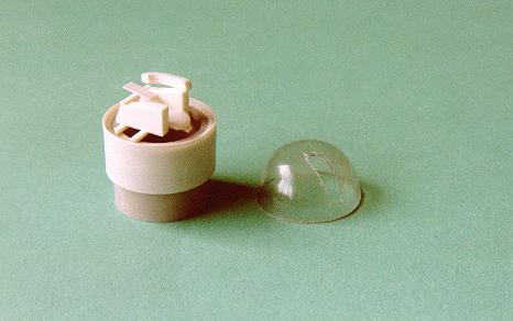
The mid-upper turret is supplied as a clear moulding, but it has no base, so I made one from a short length plastic tube with thin plastic card wrapped around it to increase the diameter to fill the aperture in the fuselage and also to provide a ledge for the clear turret to sit on. Detail was added to the interior and the whole turret assembly was simply popped into place to rest on its ledge in the fuselage - see Photo 16.
The bomb bay was detailed using lengths of I-section plastic mouldings and strips of plastic card to represent ribs and bomb racks and the doors from a Lancaster kit were shortened and cemented in place in the open position. A single actuating ram was added to the front of the bomb door.
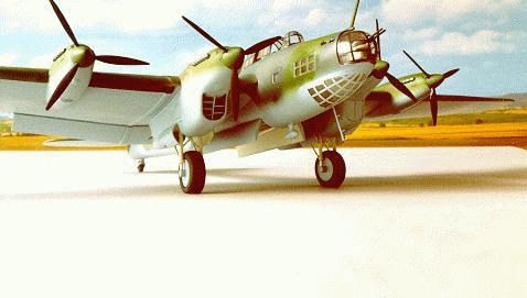
To show off the detailed cockpit, I cut the kit supplied canopy into pieces to provide a windscreen and a central fixed portion of the crew canopy. The sliding portions were added using rectangles of clear acetate carefully bent to shape. All the framing on the canopies and turrets was added using clear decal film painted to match the camouflage. Cut into strips, it was carefully applied to the glazing and a thin coat of Kleer (Future) was painted over to seal the framing in. After displaying my model at the IPMS UK Nats, I was dissatisfied with the cockpit glazing - the windscreen as supplied is too steeply raked and my sliding portions just didnt look right, so I carved a new windscreen and canopy using the M-hobby drawings to get a better shape and plug-moulded a couple of replacement parts. The finished result looks much better - the photos of the finished model show the cockpit glazing before this improvement was made..
The kit supplied D/F antenna is usable after some serious rubbing down and
the large aerial on top of the nose plus the undernose antenna with its prominent
pitot tubes were both made from plastic card and added.
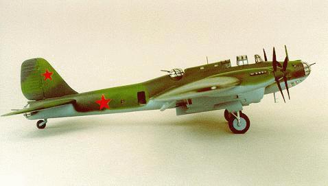
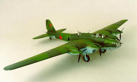
I had decided on a green and black camouflage scheme with pale blue undersides and, after some correspondence with the owners of this web page, I decided on Humbrol 150 for the bright green and 91 for the Black-Green. The Pale Blue came from a bottle of Niche Marketings Red Paint series. Aeromaster now do a range of WWII Soviet colours, but I have not yet used them.
After airbrushing the colours, exhaust stains were added using pastels and a silver pencil was used to add areas of paint chipping.
Red stars were added in six positions - wing undersides, rear fuselage and
fin and the whole model given a coat of matt varnish to seal everything in.
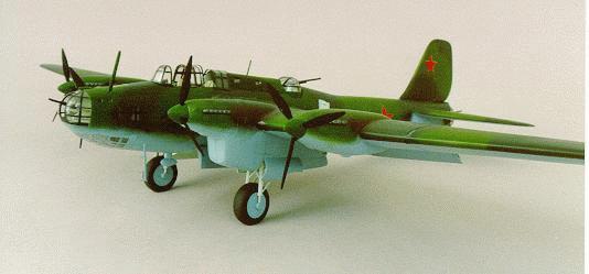
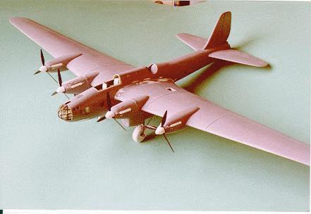
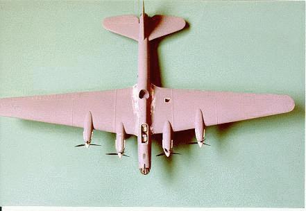
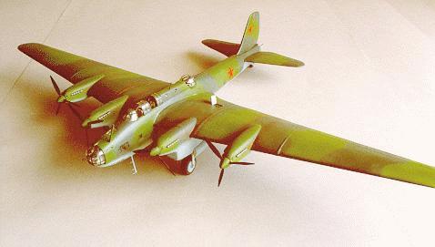
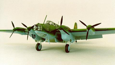
Contrails kit makes up into a fine example of the only Soviet four-engined bomber, The only major flaw lies in the length of the fuselage, but as I hope I have shown, this can easily be fixed.
The rest of my additions - flaps, bomb bay, detailed interior are down to personal preference while the scrap box should be able to provide the necessary replacement parts such as the props, tailwheel etc.
The finished model makes an interesting addition to our Soviet Aircraft Special Interest Group (SIG) display and created quite a bit of comment at the IPMS (UK) Nationals - people had either never heard of a Pe-8 or, like me, just didnt appreciate how big an a/c it really is - especially when placed next to my Soviet Lancaster !
Ken Duffey
December 1998