Modeling Russia’s Rocket Fighter Pioneer
By Malcolm V. Lowe
Modeling Russia’s Rocket Fighter PioneerBy Malcolm V. Lowe |
|
If your preferred scale is 1/72, then there is no problem in building a model of the Bereznyak-Isayev BI rocket fighter. A very credible injection-moulded kit of the BI, with parts to make up one of several of the prototypes, is widely available at present. I am not, however, aware of a 1/48 scale kit of the BI that is currently on general release.
The 1/72 scale kit that is available is from Eastern Express of Russia. I bought mine by mail-order from Hannants, who stock most of the strangely-diverse range of 1/72 scale aircraft kits in the Eastern Express line. Although this kit became available comparatively recently from Eastern Express, their BI kit is, however, most definitely not new. It has appeared a number of times over the past few years, released by a variety of kit producers. At one stage it was even for sale as a double kit, with enough parts to make up two BI prototypes from the same kit, including the BI No.6 with wing-tip ramjet installations fitted. In addition to this, at least one other, entirely separate injection-moulded kit of the BI was released a number of years ago, this different kit at one time appearing in a plastic bag with a header card stapled to it.
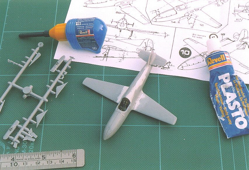
The Eastern Express kit comprises some 36 parts injection-moulded with quite heavy sprue in mid-grey plastic, with a separate rather poor-quality transparent moulding for the windscreen and cockpit canopy. A number of alternative parts are included in the kit, so that one can, for example, make up the model either with wheels or with a ski undercarriage. The ski parts included are for the earlier type skis of the early prototype(s). A small decal sheet in the kit includes tail numbers for three of the BI prototypes (Nos.2, 3 and 6), plus a couple of stencils and a number of red stars – some of which have thin white surrounds that are off-register. All this comes in a very attractive box with a nice painting of an un-numbered BI in flight on its lid, and a colour scheme side-view on a side panel of the box. The kit’s instructions are rather a disappointment, being a poorly photocopied sheet with some barely discernible construction drawings plus colour scheme details which are difficult to make out. Luckily one of my friends in the Czech Republic was able to come up with an instruction sheet from one of the previous incarnations of this kit, they are virtually identical to the Eastern Express instructions but properly printed.
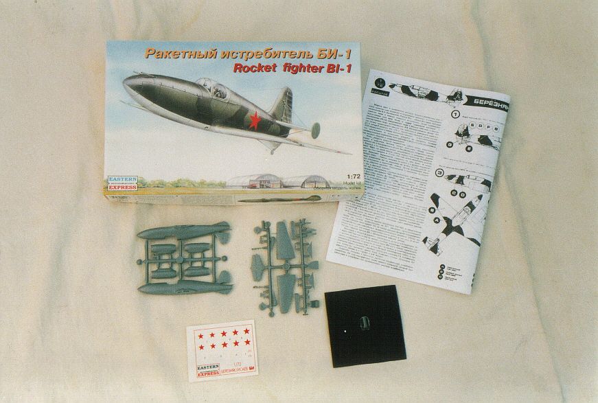 |
The contents of the Eastern Express kit of the BI rocket fighter, showing the neat contents and attractive box-art. (Photo: Malcolm V. Lowe) |
If you build this kit straight from the box you will end up with a small, neat replica of one of the BI prototypes. The kit comes with alternative parts to build the second, third or sixth prototypes, and this includes the wing-tip ramjet installations of the BI No.6 in one of its configurations. Parts are not supplied for the tailplane bracing struts of the early prototypes, nor the retraction arms for the main undercarriage that run from the undercarriage legs to the inner wheel well structure. The kit’s instructions suggest that these parts are made from stretched sprue, and a diagram is included on the instructions showing how to do this, plus the correct lengths that the stretched sprue should be cut to. On the poorly-photocopied instructions that came with my Eastern Express kit, these dimensions were illegible!
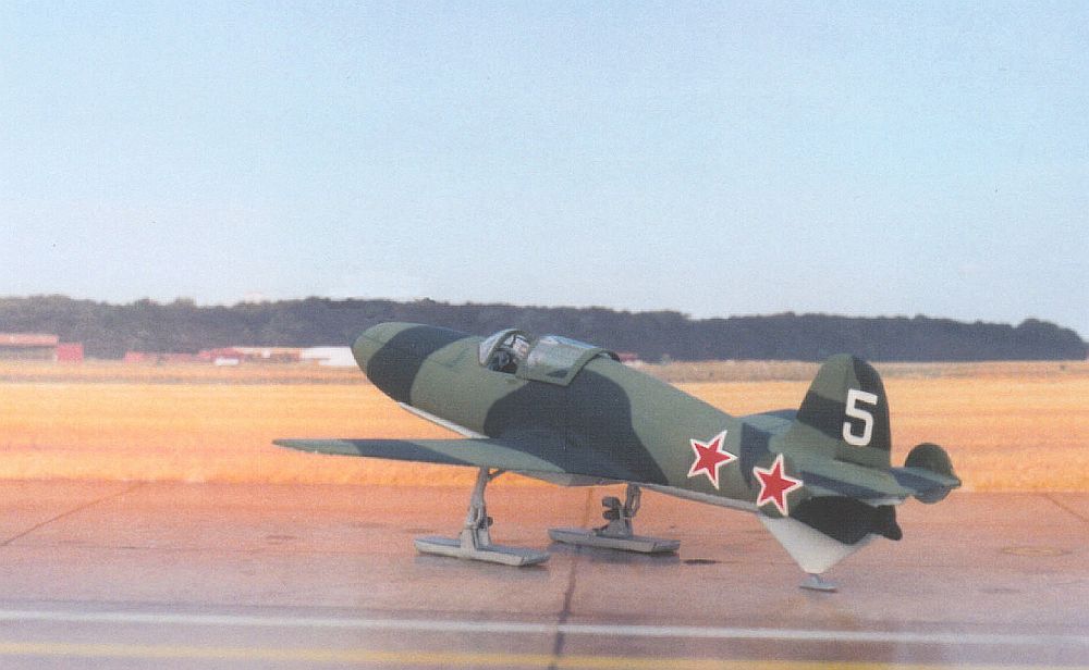
I intended from the start that this kit should present somewhat more of a challenge than a straight kit build, and so I decided to construct the BI fifth prototype, with its somewhat rough ski undercarriage and strange ‘ski simulator’ beneath the fuselage. A number of good photographs of this specific aircraft have been published over the years, allowing a reasonably accurate stab at the unique camouflage pattern that this aircraft was finished in. The following notes describe my plan of campaign for this particular aircraft, but many of the points are applicable no matter which prototype you build, so long as you bear in mind that some of the conversion suggestions refer only to the fifth prototype. This aircraft of course was not fitted with the tailplane struts, so at least I did not have to start stretching sprue, or looking out some airfoil-section struts!
The Eastern Express kit contains some rudimentary cockpit detailing that nevertheless is a good basis for more detail work if you wish. I painted the cockpit interior a grey shade (Humbrol No.64), and then dry-brushed dark grey onto the ‘detail’ that is moulded inside the fuselage halves on the cockpit side walls to make this stand out. I attached most of the kit’s interior detail parts into the right-hand fuselage side, but the rudder bar (part no.23) in particular needs to be cut down in width to make it fit properly. I added the control column (part no.36) last, after the addition of the separate keel-type floor, seat bulkhead, instrument panel, etc., to ensure that it sits in the right place in relation to the instrument panel. Strips of thin plastic were fixed to the seat to represent seatbelts. I believe that the instrument layout as moulded onto the instrument panel (part no.11) is correct for the BI No.5 (it is certainly correct for at least some of the earlier prototypes), but note that the No.6 aircraft had a different instruments layout (if we are to believe a photograph printed in ‘Polygon’ magazine, 3/2000).
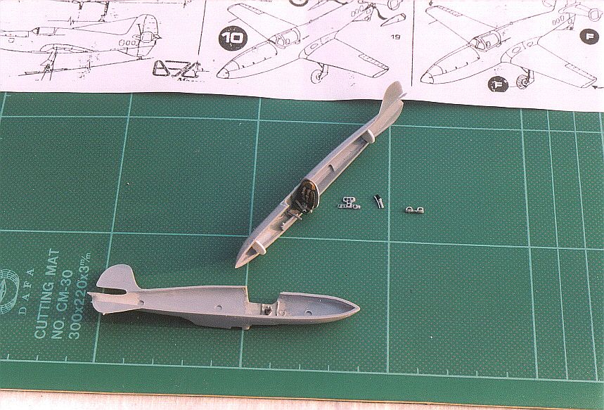 |
Construction and painting under way of the BI’s cockpit interior, using some of the kit’s cockpit parts including the instrument panel, rudder pedals and control column. Note the two bulkheads from scrap plastic that I built into the right-hand fuselage side to help line up and locate the fuselage sides. (Photo: Malcolm V. Lowe) |
The location of the left and right-hand fuselage sides in relation to each other is somewhat hit or miss as no locating pins were present on my example, and so I built in two bulkheads from scrap plastic into the right-hand fuselage side to aid in alignment of the fuselage sides and to strengthen the fuselage joint when the sides were fixed together. The rearmost of these two bulkheads also served to give an inner blanking surface within the jetpipe area. I then used gel-type superglue to affix the two fuselage sides together – the idea was that this would give a good strong joint and fill any gaps. Unfortunately there is a mis-alignment of the kit’s fuselage sides that results in a lot of filler being needed to build up the left-hand fuselage side on the spine of the fuselage. Some filler was also needed below the nose as well, and on the leading edge of the fin to build that up too. I later filled the two gun ports on the forward upper nose, as these did not apply to my aspirations to build the BI No.5 which did not feature nose-mounted weapons. Some of the other prototypes also were not armed, and so it is important to bear this in mind when building your model. On the kit’s original mouldings there is a small bump on the upper nose near to the gun ports. This is believed to be a camera gun installation, and so I removed it from my model because again this was not carried by the BI No.5. In addition, I ‘straightened’ the rudder hinge line on my model, because the fifth prototype had a straight rudder hinge line rather than the slightly curved upper section as featured on the kit’s mouldings and on some earlier BI prototypes.
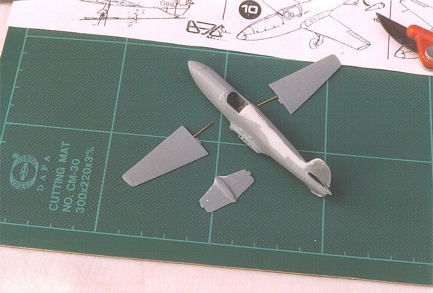 |
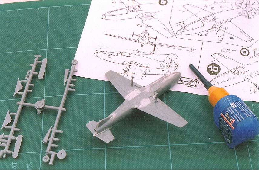
Wire locating pins were fixed into the wing pieces to locate them accurately to the fuselage, and to ensure the correct incidence and dihedral angle. Note the large amount of filler on the fuselage spine and fin leading edge. (Photo: Malcolm V. Lowe) |
The wings are supplied in the kit as a single moulding on each side (part nos. 20 and 21). The wing root fairings for these are moulded onto the fuselage sides, but something is wrong with these because one is moulded ahead of the other when you look down on the fuselage from above! This would result in one wing being mounted ahead of the other if remedial action was not taken. In addition, the incidence of each wing when viewed from side-on also does not look to be the same on each side. Therefore I went to work with a file and filler, to make the fairings equal when viewed from the top and from the side. The wings themselves could then be added to the fuselage. Each wing moulding has a little moulded tab to aid its attachment to the wing root fairings. This tab looked a little shallow to me. Mindful of how easy it is for a model’s wings to lose their dihedral angle after construction and look ‘flat’ when the model is viewed from the front if there is not much to hold the wings in place, I drilled into each wing and inserted a length of wire into each. The wire was fitted so that it protruded to act as a solid locator pin for each wing section. A corresponding hole was then drilled into each wing root fairing to locate these new wire locating pins. This ensured that when I superglued the wings to the fuselage, the wings were at the correct dihedral angle when viewed from the front, and at the correct incidence when viewed from the side.
 |
Filler was needed around the wing-to-fuselage joints, as well as on the top of the fuselage (Photo: Malcolm V. Lowe) |
Some filler was required on the resulting wing-to-fuselage joints. Two streamlined bumps are included on the kit’s mouldings on each wing root fairing. These were fitted to the BI No.5 (and indeed to the sixth prototype as well, at least for a part of the time), and so I left them in place on my model. The earlier prototypes do not appear to have carried them, and so if you are modelling one of the earlier BI aircraft then it is wise to file them away.
 |
The kit’s main undercarriage legs have been added by this stage. Note the areas of light-coloured filler underneath at the wing-to-fuselage joints. (Photo: Malcolm V. Lowe) |
The horizontal tailplane piece (part no.13) is moulded in one piece that is intended to slot into a cut-out at the base of the fin and rudder in the rear fuselage. It slots in neatly enough, but some filler was necessary around the resulting joints particularly underneath it. The outer edge of the moving part of the horizontal tail is curiously moulded on each side as a diagonal when viewed from above, it should be parallel to the line of flight and so I cured it with a file. I added the tailplane endplate fins (part nos.10 and 16) later in the construction and painting sequence.
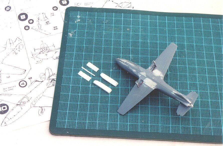 |
In order to make the BI No.5, I scratch-built the ‘ski undercarriage simulator’ pieces beneath the fuselage from scrap plastic. This involved five main scratch-built parts, including the small ‘rail’ that fits on the centreline between the two forward strengthening panels. (Photo: Malcolm V. Lowe) |
The main undercarriage legs (part nos.12 and 14) were damaged in my kit, in that the scissor links to the oleo section were broken. I therefore cut them away and replaced them with thin scrap plastic. These fit at the back of the leg for most of the prototypes (including my BI No.5), but appear to have fitted in front on the first machine. The retraction member that runs from each main undercarriage leg inboard into the main undercarriage well on each side needs to be added from stretched sprue – it fits onto the back of the leg for most of the BI prototypes, but appeared to be attached to the front of each leg on the original BI example.
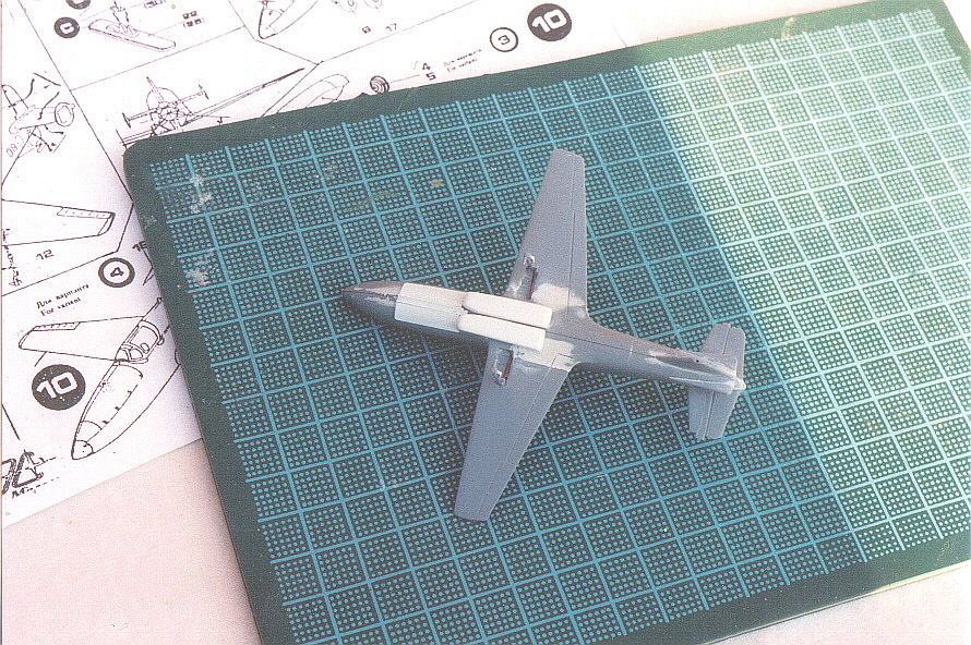 |
The various pieces to make the under-fuselage ‘ski undercarriage simulator’ and related fitments have been fitted in place by this stage, and the model is ready for painting. (Photo: Malcolm V. Lowe) |
During construction the moulded pitot extending from the right-hand wing leading edge broke off, and so I replaced it at the end of the construction sequence with a suitable length of stretched sprue.
As previously related, I intended to build my model as the fifth BI prototype, and this required some additional work to make this specific aircraft.
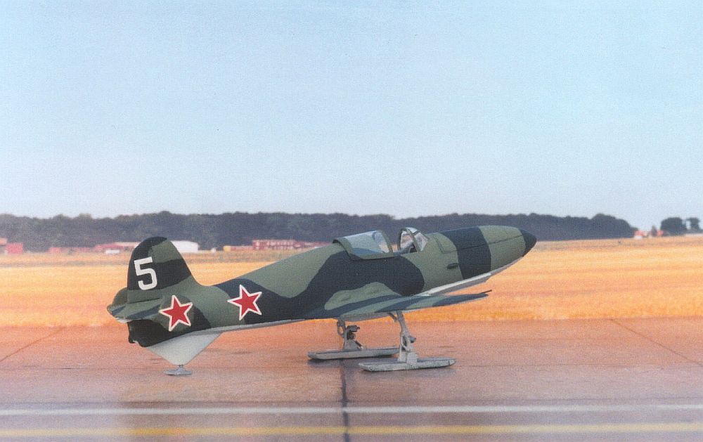 |
Picture of the completed model. (Photo: Malcolm V. Lowe) |
The ventral rear fuselage fairing for the rear undercarriage member is moulded integral with the fuselage halves in the Eastern Express kit. However, it has the curved rear edge and slightly different shape as featured on the early BI prototypes. The BI No.5 had the later, straight edged fairing, as did the sixth prototype. Parts for this different fairing are included in the kit as alternative pieces (part nos.31 and 33). I therefore removed with a razor saw the existing fairing moulded beneath the rear fuselage, and substituted the alternative fairing made up from parts 31 and 33. The BI No.5 also had two streamlined fairings beneath the tail on the sides of the rear fuselage, and these are also included in the Eastern Express kit as alternative pieces (part nos.18 and 19). These were fixed onto my model – they are not applicable for some of the earlier prototypes, but they are also essential for the BI No.6.
The most major work to make the BI No.5 involved the undercarriage and under-fuselage fairings. As related elsewhere in this feature, the BI fifth prototype featured rather crude skis that seem to have been different to those fitted to the early prototype(s). The BI No.5 also carried the curious structures beneath its fuselage sometimes called a ‘ski simulator’, plus a centreline ‘rail’ below the forward fuselage and what appears to be a strengthening panel on each side of the rail. I scratchbuilt all these various parts from scrap plastic. Good reference is provided for these fitments in the ‘Polygon’ magazine (3/2000) also referred to elsewhere – although reference to the photograph of the BI No.5 accompanying my historical feature on the BI is a good starting point for the skis. These skis are rather more crude (and apparently thicker) than the skis fitted to at least one of the earlier prototypes, and so I built the skis for my fifth prototype from scrap plastic, using the kit’s skis as a guide to overall size (length and width). The kit’s skis appear to represent those as fitted to one of the earlier machines. The colour of the BI No.5’s crude skis is completely debatable – they had the appearance of being simple planks of wood. I painted mine Humbrol No.64 grey for lack of a better alternative. As for the rear ski beneath the tail, I used the kit’s ski part no.27 as this appears to have been similar on the fifth prototype to that used on the earlier prototype(s).
The BI No.5 (and also the sixth prototype) featured a small fitment on its right-hand fuselage side just ahead of the cockpit that appears to have been a venturi. I added this onto my model from thin plastic rod.
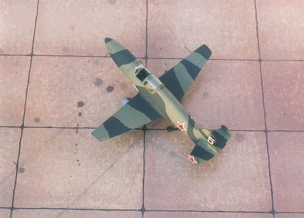 |
Picture of the completed model. (Photo: Malcolm V. Lowe) |
The clear plastic cockpit canopy/windscreen moulding provided in my example of the Eastern Express kit was very thick and not very clear. I therefore moulded a new one out of clear 10 thou plastic sheet, using the simple male/female method with the kit’s component acting as the male part of the mould. I usually install the moving portion of the cockpit canopy on my models in the open position, and so I carefully cut my ‘new’ moulding where applicable to make it into a windscreen and separate canopy. I affixed the new windscreen with PVA glue, and added the rearward-sliding canopy in the open position when the model had been painted.
This is where we come into some controversy. However, the following is how I finished my model.
Knowing the controversial nature of the subject, I contacted Erik Pilawskii for his thoughts. Erik is the author of the excellent book on Soviet air force colours in the period 1941 to 1945 referred to elsewhere on this web-site, and he feels that the BI prototypes were most probably painted initially in AII black and AII green on the upper surfaces, and AII blue beneath. These colours over the years have come in for much speculation and re-naming in published sources, although it is also worth noting that Soviet air force colours were by no means consistent from one batch of paint to another, nor in their source. However, if anyone reading this article can honourably disagree with these points by producing original Soviet documents and genuine witness testimony to the contrary, then I will be pleased to hear from them.
For the record, the Eastern Express kit’s instructions sheet contains colour scheme details for the second, third and sixth prototypes. For the Nos.2 and 3 the instructions suggest a scheme of “dark green” and “grass green” for the upper surfaces, and “light blue” for the undersides; and for the No.6 with the wing-tip ramjet installations, the instructions suggest “light grey” and “medium grey” on the upper surfaces, and “light blue” underneath. For the BI No.6 when it had a conventional undercarriage attached, without the wing-tip ramjet pods, the instructions suggest “light grey” on top and “light blue” underneath.
I painted my model of the BI No.5 in the colours suggested by Erik Pilawskii, with the black ‘toned-down’ to black-green. The colours that I used were:
Before anyone complains of the use of Xtracolor No.X606 in this context, in my defence I think that this paint is a very useful source for the underside blue. As a digression, it is not bad either for World War Two Luftwaffe RLM 65 Hellblau (I feel that Xtracolor No.X202, which is claimed to represent No.65 Hellblau, is far too dark and mid-blue for that colour). Unfortunately, Hannants (who market Xtracolor paints) have apparently now discontinued the manufacture of X606, which is a shame because it is very useful for applications much wider than the Mil Mi-24 helicopter colour to which it primarily applies. Think again Hannants, and reinstate X606 to production immediately!
It is, incidentally, worth noting that a new range of model paints depicting Soviet World War Two colours has recently been released. These paints are produced by White Ensign Models in Britain and are a welcome addition to the paints that are currently available and purport to represent Soviet air force colours.
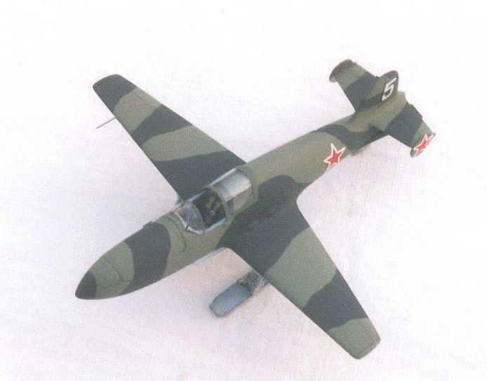 |
Picture of the completed model. (Photo: Malcolm V. Lowe) |
After I had applied a coat of gloss varnish over the top of my now painted model (the Xtracolor paint is shiny already) I applied the transfers from the Eastern Express decal sheet. The white numeral ‘5’ on the tail of my model was made up from the numeral ‘6’ on the kit decal sheet, suitably modified and touched-in with a small paintbrush and white paint. The underwing red stars without a white border were again from the kit decal sheet, these being annotated on the sheet with the letter ‘B’. For the fuselage and endplate fin stars I used the red stars with a white outline from the kit decal sheet that are annotated ‘C’. I have yet to find a sheet of decals featuring red stars with white outlines where the printing is in register. The white outlines on my kit decal sheet were no exception, and so after application of the stars I touched in the white edges with white paint and a small paintbrush to try and even them up. There is a school of thought that suggests that these edges might have been yellow, but without a colour photograph of the fifth prototype this is difficult to verify for certain.
A final coat of matt varnish finished the job. I use Daler-Rowney ‘Cryla’ artists’ matt varnish, this is a proper MATT varnish and not one of the many shiny so-called “matt” varnish products that proliferate nowadays. The overall result is a small, neat model of an unusual subject. It scales out reasonably well against the dimensions quoted in the 2nd edition of the book ‘Soviet X-Planes’ by Gunston and Gordon, and is an extremely eye-catching if very small model in 1/72 scale.