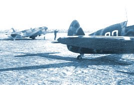
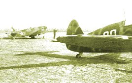
please forgive the small size and low resolution of this
image; a proper version of this photograph will appear in my
upcoming book
The Yak-7 Photograph
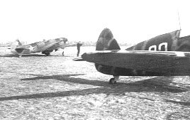
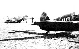
During 1943, a Yak-7 of just such brilliant work
was photographed on the southern edge of the Kursk front. The unit in question,
alas, was not recorded on the photograph caption, but the location of the airfield
does narrow the possibilities to a degree. Further, this scheme is highly reminiscent
of the three-color South Front applications that were known to have been executed
by units like the 146, 248, 273, and 431 IAPs. Of these Regiments, both the
146th and 248th were located in the area where this photograph was taken during
the summer of 1943, and included Yak-7s on their strength. It is possible that
this Yak-7 belong to either unit, or neither, but their earlier experience to
the South might have influenced just such a camouflage application.
Once the photograph has been located and the availability
of the negative determined, the image is then scanned into a digital format
with care. Considerable attention must be paid during the scanning process to
avoid alteration to the image, and the color values (hue, chroma, gamma, etc.)
represented on the picture. It is much easier to analyze any anomalies in
the appearance of the photograph by manipulating an exact scan of the image,
rather than by the manipulation of the scanning process. If the photographic
negative is available, digital image processing is usually not required, and
the goal in the scanning process is simply to produce the most attractive appearance
possible. Negatives reveal a tremendous amount of information about the resulting
photograph (the film type used, lighting and camera settings, processing errors,
etc.), and a properly verifiable analysis of the picture is usually possible
with the negative in hand.
In this case, however, the photographic negative is not available.
Therefore, one's analysis must return to the digital image created during the
scanning process. Many separate techniques are employed, and it is best to complete
these examinations with several different software packages so as to mitigate
any specific curiosity within any one computer program. Expertise in the use
of this kind of software is helpful.
 negative image
 hi-contrast examination
 channel splitting
Through these examinations, the idea is to try to work out
the most likely colors in view, as well as the demarcations for the colors in
the pattern. Evidence from other objects in view, such as the grass and sky,
etc., and the appearance of the additional aircraft, can be invaluable. In this
case, the Yak-7B (w/cut-down fuselage) in the background is a tremendous help--
it is wearing a clearly identifiable factory applied camouflage scheme about
which a good deal is known. Happily, the scheme in question is known only in
the specific colors of AMT-6/AMT-4/AMT-7, and a direct comparison can then be
made between the two aircraft's appearance.
After extended analysis, the coloration is thought to most
likely consist of AII aerolacquers; in this case Green, Black, and Light Brown.
The visible pattern has clearly been modified from its factory finish, but several
clues point to a very possible identification. Noting the general arrangement
of the rear fuselage and vertical fin, and also the leading edge of the wings,
it seems that this Yak-7 may well have been finished originally with a 'Loops'
pattern (a most attractive camouflage pattern first developed by the indefatigable
Nadia Bukhanova) as applied at Zavod 153 (Novosibirsk) during 1942-43.
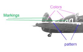
The photograph is then examined for clues as to the markings--both national
and tactical--applied to the aircraft, and any personal markings or identification
visible. The numeral on the fuselage is rather obscured. However, a close inspection
of the second number seems to show a break from the top 'loop' consistent with
a squared-font "3". The first number could certainly be another "3", a "0",
an "8", or possibly a "9".
 details of the aircraft's finish
Finally, any details that may identify the aircraft type are examined. The tail wheel cover on our subject machine is of the earlier, forward folding type. However, the aircraft features a radio mast and rear fuselage plywood cover of a type that indicate strongly that the machine is a Yak-7B. This idea is supported by the likely timing of its manufacture taking into account the type of camouflage in which it was originally finished.
Other Evidence
After the photograph is analyzed, the next step in the process
is to attempt to locate other sources of information about the subject aircraft.
Searching through the available reference material for additional photographs
is a good start. As well, drawings or profiles completed by other authors or
artists can be valuable; sometimes these are executed from additional unknown
resources or pictures. It is also valuable to compare one's own conclusions
with another researcher; such a comparison may reveal further insights. In the
case of our subject Yak-7 aircraft there are no further known photographs, and
this image appears not to have been published previously. No additional profiles
or drawings of this aircraft are known.
In my own research on VVS subjects, I rely mainly on the
photographic evidence that I have collected over the years. In my case, I keep
a notebook (well, many, as a matter of fact) of all of the photographs that
I have ever seen in any collection; I have done this faithfully since 1987.
For each photograph I make a description using a notation system of my own invention
to describe the subject(s) of the photo. The collection, reference number, negative
information, caption information, and date are all recorded, if available. In
many cases, a small sketch accompanies the description in the margin. The grand
total over the years has come to many thousands of Notebook entries, needless
to say, but certainly not all of these are unique examples; many photographs,
or copies thereof, are to be found throughout a number of collections.
Now, searching through this large database of photos, I of
course looked for any entry with similarities to the subject at hand. I turned
up eight Yak-7s with 3-color camouflage; six of these were Yak-7 'razorback'
models; five were Yak-7Bs; four wore similar coloration schemes (AII Green/Black/Lt.Brown);
two featured pattern applications involving an outline of the normal pattern.
Of these two entries, one clearly was not our aircraft-- the Notes entry describes
"Red 25" of the 273 IAP at Stavropol (in the Caucasus); clearly not the same
machine. However, as it turns out, in 1990 I happen to have seen the same--or
a very similar--photograph in the collection of the Gosudarstvenniy Musey
Aviatsii, Leningrad (now Skt. Peterburg). This picture, however, gave a
slightly wider view (up to the no.3 exhaust stack to stbd.). The Notes I made
at the time seem to confirm the current suspicions: the scheme was described
as "a modified Loops application with outlining of the pattern in Lt.Brown";
the number was estimated to be "03(?), in white, just aft of cockpit"; and the
Yak-7B in the background ("Red 41") was also described as it appears in this
view.
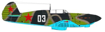
The Color Profile
With all aspects of the photograph examined in full, and
all corroborating evidence addressed, the next step is to create a color profile
of the subject aircraft. Although I was fairly satisfied that the colors on
our Yak-7 were AII lacquers, I elected to complete the profile in AMT paints
as well, just for comparison's sake. The results were fairly satisfactory.
 AMT-1/-6/-4 finish
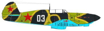 AII Green/Black/Lt.Brown finish
The next step is to create a black-and-white image (known
as 'greyscale') out of these color drawings. Making an accurate 8-bit greyscale
image can be extremely problematic. The difficulty here is that most graphics
and photographic manipulation software use a different set of calculations and
algorithms to transform the color image to a greyscale one. Therefore, the results
from using and Adobe product to produce an 8-bit greyscale image will
differ greatly from using a Jasc package, and so on. This problem is
further exacerbated by the myriad ways in which different video card/monitor
combinations draw images on your screen, and even by the Operating System on
your computer.
On my own PC, my experience has been that Jasc's Paint
Shop Pro produces greyscale 8-bit images which are very similar to the appearance
of aircraft on Soviet K-16/39 film (the most common type). This is certainly
no guarantee that it may do so on anyone else's computer; it is simply
that way on mine. Thus, using the color profiles I created, a greyscale image
was generated.
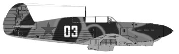 AMT greyscale
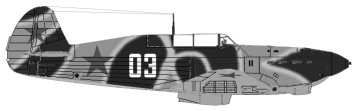 AII greyscale
From this experiment, it seems all the more clear to me that the AII color
interpretation matches the appearance of the actual Yak-7 in the photograph.
I would not rule out the possibility that the photo shown
an aircraft in AMT aero paints, but on balance this seems to be the less likely
of the two options. The subject aircraft could also be wearing an exotic combination
of disparate colors, as well (such as AMT and AII paints both, or AE-9, or some
type of primer); these options are impossible to test for, practicably, and
in my own view are very much less likely than an explanation with standard
paints.
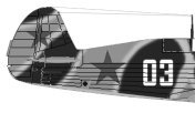
The color profiles may be viewed here: starboard
view top view
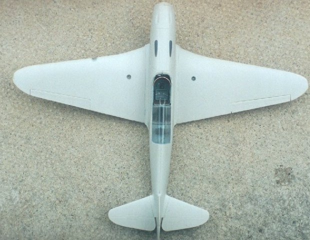
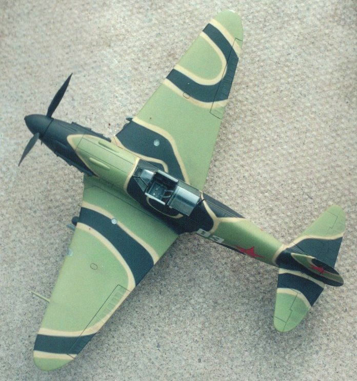
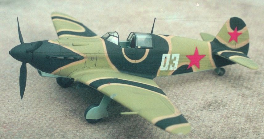
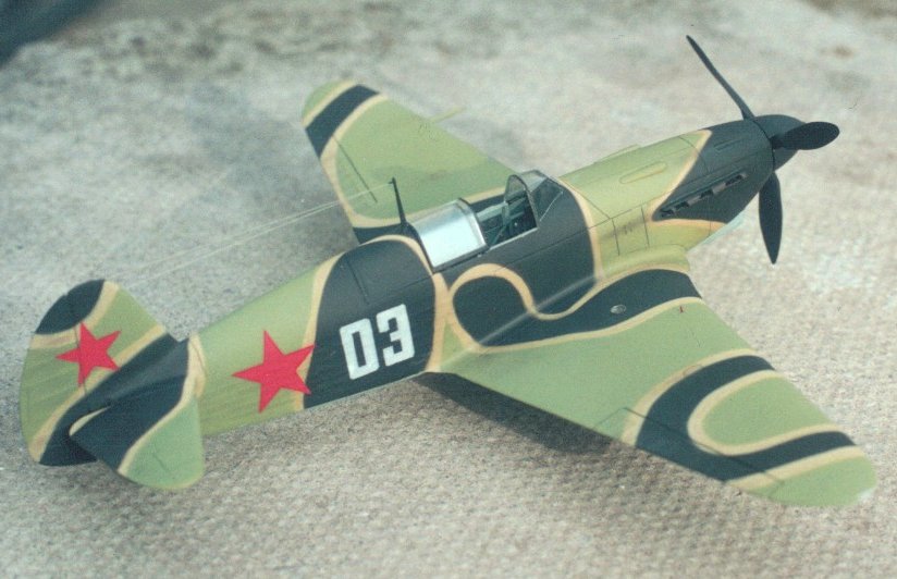
A Scale Model
With the color profile of the aircraft completed to satisfaction
(speculations and all), it occurred to me that a model of this fantastic Yak-7
would be a necessity. Only in a three-dimensional object, I surmised, would
the full impact of such a scheme become clear. With only mediocre modeling skills
myself, I cast an eye towards other more experienced model builders to complete
the project. Fortunately, our delightful Hero of Soviet Modeling Peter
Vill agreed to take up the challenge. Peter works in 1:48 scale, and the
excellent ICM kit was selected for the job.
After a review of the project, Peter elected to use a very
new shade of AII Green. I duly mixed some bottles of AII Green (new) and AII
Lt. Brown and dispatched these to Peter. The paints were accompanied by some
suitable "03" decals, these printed on my ALPS MD1000 cassette ribbon printer.
With all of the necessary supplies in place, I waited with wringing wrists for
the final product....
"Nadias YAK"
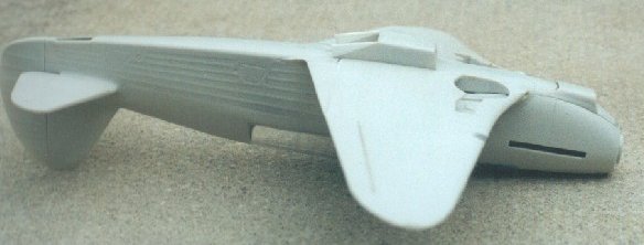
Building the ICM YAK-7A or as it turned out a 7B
by Peter Vill
When Erik visited the U.K. in May of this year he took time to stay at the Vill family home. I introduced him to real ale and Cleeve Rugby Club (don't worry Erik I won't mention the billiard table and the lady in the tight black dress), he in turn introduced me to and some art work involving a three colour scheme YAK-7b. After more Vodka than I care to remember he asked if I would make a model of this 3 tone YAK; at this point I said something like "NO, dont be a fool" but it came out as a slurred "Yes, no problem, pass the ice cold vodka".
Now at the time I had a ICM 1/48 kit of a YAK-7a in my stock, but ICM also make a 7b, could I find one?-- NO. I decided that to convert the A into a B would not be that hard, this is how it went (oh yes, and by the way Pilawski I am not mixing , you and art work again).
The main external difference between the two marks of 7 are the cowling bulges that incorporate the 12.7mm machine guns on the B instead of the 7.62mm machine guns used on the A, the under wing radiator housing is also a different shape. The aircraft that Erik had asked me to model was also fitted with exhaust glare shields and the exhaust pipes exited the cowling via a long slot instead of the individual openings.
The kit itself is typical of what we have come to expect from ICM, with a little work you can produce a beautiful model, you will be hard pressed to find better value for your money apart from Eduard. The kit appears to contain all the parts to build a two-seated trainer or a single seated fighter complete with wheels or skis. As usual an engine and fuselage framework are included, the only fault is the rather thick canopy that is best replaced with an item from the Falcon range.
The model would be finished without the engine so those bits went straight into my spares box (If anyone reading this wants the engine let me know), so work commenced on the cockpit floor/seat assembly. The seat and armoured back plate were thinned down to achieve a more in scale look and then seat belts from the Re-Heat range were fitted. Next were added some heel boards to the cockpit floor and the rudder pedals that had been detailed slightly, the assembly was then put to one side until required.
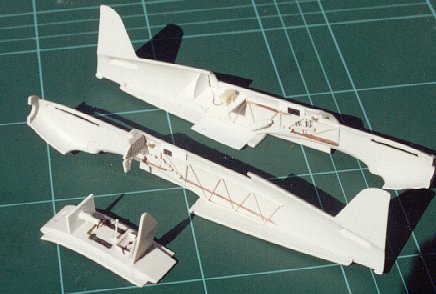
All of the interior assemblies were then primed and sprayed with my interpretation of MUP, detail painting and dry brushing being carried out before being given a coat of "Halfords" gloss varnish.
Before the parts that form the wing were put together I drilled out the fuel gauges and represented these by fixing plastic card to the inside of the wing, I then fix a decal to the plastic card and finally represent the gauge lens with a punched out circle of clear plastic card stuck into place. Wing assembly then follows the kit instructions, when dry the wing is fixed to the fuselage. As with all the ICM kits that I have built so far very little trimming or filler was required to get a first class joint. When the wing joint had been sanded down I attached the two wing tip navigation lights and the single landing light, when dry these were filled and sanded, the joints of these clear lens being polished up with squadron sanding sticks supplied by Antics of Bristol.
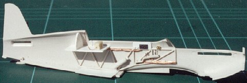
The gun sight mounting ring was replaced using a bit of copper wire curved to fit, the gun sight being made from scratch, a little piece of clear plastic representing the reflector lens. I wanted to show the canopy in the open position so I cut the rear section off the kit canopy, which is rather thick and attached this to the model, the front and sliding section being replaced with items from the Falcon set number 37. Falcon tell you to cut away a section of the fuselage if you want to use the late 7 canopy, I didnt. Ok I admit to not reading the instructions until it was time to fit these parts, so I had to tape the replacement front section of the Falcon canopy into place and mark the excess that was required to be removed; it fitted first time.
When the canopy had been blended in it was time to think about the exhausts and the glare shields. The anti glare shields were remarkably easy to make, I simple folded some 10 thou plastic card around the exhaust, cut them to length remembering that the shields extend past the last exhaust pipe, shaped the ends and then stuck them to the exhaust pipes, when dry I placed the exhausts into the slot and glued them into place. Please note that at the time of attaching the exhausts that engine top cowling (kit part D7a) had not been put in place, this was left off as it allows access to the exhausts from inside to add bits of plastic card to ensure a strong fixing, also the cowling requires modification to represent a 7b.
The cowling modification is quite simple, a length of plastic rod is sanded down at the end to approximately 45 degrees, cut to length and rounded at the thicker end, this is then attached to the cowling in line with the machine gun openings (Refer to your scale plans for the correct position). When this operation is completed the cowling can be fixed into place.
The scale drawings in the A. J. Press Aircraft Monograph No 14 YAK-7/YAK-9 show that late 7`s had a different shaped radiator housing under the wing, this is also seen in a number of photos, a little plastic card soon altered the shape. Due to the alteration of the radiator housing the kit supplied radiator shutter (Part No D13) could not be used, a replacement was soon made from printers litho plate.


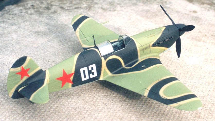
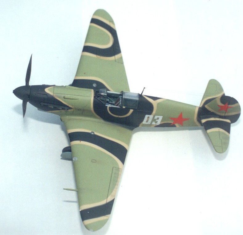

Conclusions
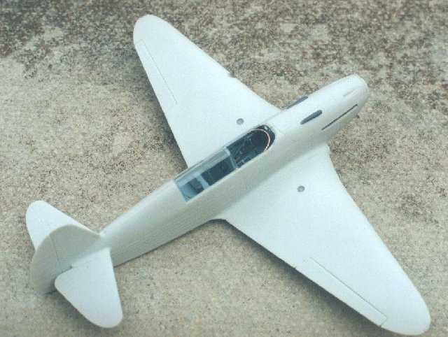
Well, I for one think that the model produced by Peter is
outstanding. As well, it think it gives an accurate representation of the likely
appearance of this wonderful Yak-7B fighter. As often happens with such interpretations,
some questions remain. What is the actual tactical number? Are AII colors correct?
What does the port side look like? Modeling--and aviation research, as a amatter
of fact--can sometimes be a matter of educated speculation.
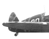
On the other hand, Peter has done his job well. I have produced
a greyscale image of this model using the same techniques as above. However,
in this case some change in the relative lighting values were made, noting that
Peter's model was photographed outdoors with light from directly overhead, and
in our subject photo the light is from well to port, and the starbord side is
in shadow. Examine the resulting 8-bit greyscale, and judge for yourself (the
inset image shows an unmodified version).
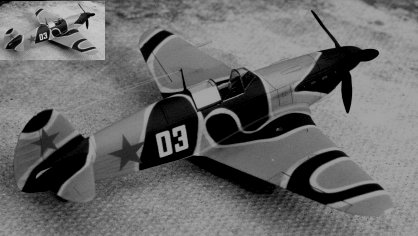
Well done, Peter Vill.